RLC-SVX19G-GB
136
4 UNT-PRC002-GB
Technical Data
FWD 08 12 20 30 45
Power supply (V/Ph/Hz) 230/1/50
Capacities
Cooling capacity on water (1) (kW) 5,2 8,3 15 18,8 30,1
Heating capacity on water (2) (kW) 6,3 11,9 18,9 20,9 38,2
Fan motor (type) 2 x direct drive centrifugal
Fan power input (3) (kW) 0,23 0,46 0,65 1,04 1,51
Current amps (3) (A) 1,1 2,2 3,1 4,7 5,5
Start-up amps (A) 3,2 5,5 9,3 14,1 16,5
Air flow
minimum (m
3
/h) 490 980 1400 1800 2700
nominal (m
3
/h) 820 1650 2300 3000 4500
maximum (m
3
/h) 980 1970 2600 3600 5400
Main coil
Water entering/leaving connections (type) ISO R7 rotating female
(Dia) 3/4" 3/4" 1 1/2" 1 1/2" 1 1/2"
Electric heater (accessory for blower only)
Electric power supply (V/Ph/Hz) 230/1/50 230/1/50 or 400/3/50 400/3/50 400/3/50 400/3/50
Heating capacity (kW) 2/4 8 10 12 12
Hot water coil (accessory for blower only)
Heating capacity (4) (kW) 6,3 12 17,4 22,4 34,5
G2 filter (filter box accessory)
Quantity 2 2 2 2 2
Dimensions ( LxWxth) (mm) 386x221x8 486x271x8 586x321x8 586*421*8 586*621*8
G4 filter (filter box accessory)
Quantity - 2 2 2 2
Dimensions ( LxWxth) (mm) - 486x264x48 586x314x48 586*414*48 586*614*48
Condensate pump (accessory) (type) Centrifugal
Water flow - lift height (l/h - mm) 24 - 500
Not available for FWD30 and FWD45
Sound level (L/M/H speed)
Sound pressure level (5) (dB(A)) 36/40/43 38/41/44 46/50/53 47/52/57 47/52/58
Sound power level (5) (dB(A)) 46/50/53 48/51/54 56/60/63 57/62/67 57/62/68
Unit dimensions
Width x Depth (mm) 890 x 600 1090 x 710 1290 x 820 1290 x 970 1290 x 1090
Height (mm) 250 300 350 450 650
Shipped unit dimensions
Width x Depth (mm) 933 x 644 1133 x 754 1333 x 864 1333 x 1008 1333*1133
Height (mm) 260 310 360 460 660
Weight (kg) 32 46 61 76 118
Colour galvanised steel
Recommended fuse size
Unit alone (aM/gI) (A) 8/16 8/16 8/16 8/25 8/25
Unit with electric heater (gI) (A) 16 (2kW),25 (4kW) 40 (230V),3*16 (400V) 3*20 3*25 3*25
(1) Conditions: Water entering/leaving temperature: 7/12 °C, Air inlet temperature 27/19°C DB/WB - Nominal air flow
(2) Conditions: Water entering/leaving temperature: 50/45 °C, Air inlet temperature 20°C DB - Nominal air flow
(3) At high speed with nominal air flow.
(4) Water entering/leaving temperature 90/70 °C, air inlet temperature 20 °C DB, Nominal air flow.
(5) A rectangular glass wool duct 1m50 long is placed on the blower.The measurement is taken in the room containing the blower unit.
Heat exchanger operating limits:
FWD:
*water temperature: max 100° C
*absolute service pressure: min 1 bar/max 11 bars
Accessories - Hot water coil:
*water temperature: min. +2° C/max. 100° C
*absolute service pressure: min 1 bar/max 11 bars
Optional Free-Cooling
Note for installation
All Submittal, lifting diagram, neoprene pads positioning
and wiring diagrams have been supplied with chiller
order.
The maximum pressure of the Glycol side when unit
is equipped with free cooling is 400 kPa for Glycol
free option or 600kPa for Direct free cooling except on
evaporator side for glycol free 1000 kPa Refer to unit
nameplate for rated value.
Pump operation with Glycol free : it is requested to have
a minimum water side pressure of 250 kPa to avoid
cavitation.
Glycol free option : To avoid component damage, a filter
(1 mm mesh) must be supplied by the customer and
installed at the unit inlet.
Unit is shipped without glycol content on the free cooling
circuit.
Free cooling loop venting must be performed by using
Manual override mode to run the free cooling pump and
opening free cooling and closing bypass valve.
At 10 to 20°C ambient, the expansion shall be pressurized
at 250 kpa. It should be checked when glycol loop is not
yet filled or glycol pressure is near zero.
All Free-cooling units must be freeze-protected with at
least 30% Ethylene Glycol in the cooling loop circuit
which is the most convenient percentage in order to
protect the unit against freezing. Upon receipt, make sure
that there is no remaining test water in the free cooling
circuit as it may freeze during winter periods.
Protection coverage with 30% Ethylene Glycol:
- Freezing point without burst effect = -13°C
- Freezing point with burst effect = -50°C.
Water can be trapped in BPHE and specific care must be
taken to remove it completly from BPHE during off mode
if drainage is the winter protection chosen.
The free cooling option circuit consists of copper,
carbon steel, cast iron, zinc, synthetic rubber, brass, and
Aluminum AA3102, AA3003, AA4045 in addition to other
materials that may be in the building loop connected
to the chiller. The inhibited glycol solution should be
selected at desired concentration to ensure adequate
inhibitor content. It is not advised to dilute a stronger
concentrate due to inhibitor dilution. Glycol fluid should
be free from foreign solid particles. A maintenance
schedule should be selected per the glycol manufacturer’s
requirements to insure adequate protection during
product usage.
Notice: Equipment Damage!
Failure to follow instructions below could cause
equipment damage.
DO NOT USE UNTREATED WATER. Glycol solution
must be utilised with the Direct Free Cooling option.
Glycol percentage should be based on freeze avoidance
requirements. The glycol solution requires an inhibitor
package to be carefully chosen with the aid of a qualified
water treatment specialist to abate corrosion in a mixed
metal system.
The building glycol loop should not be vented to
atmosphere. A closed system is required to limit
oxidation potential within the loop.
Make-up water should be avoided.
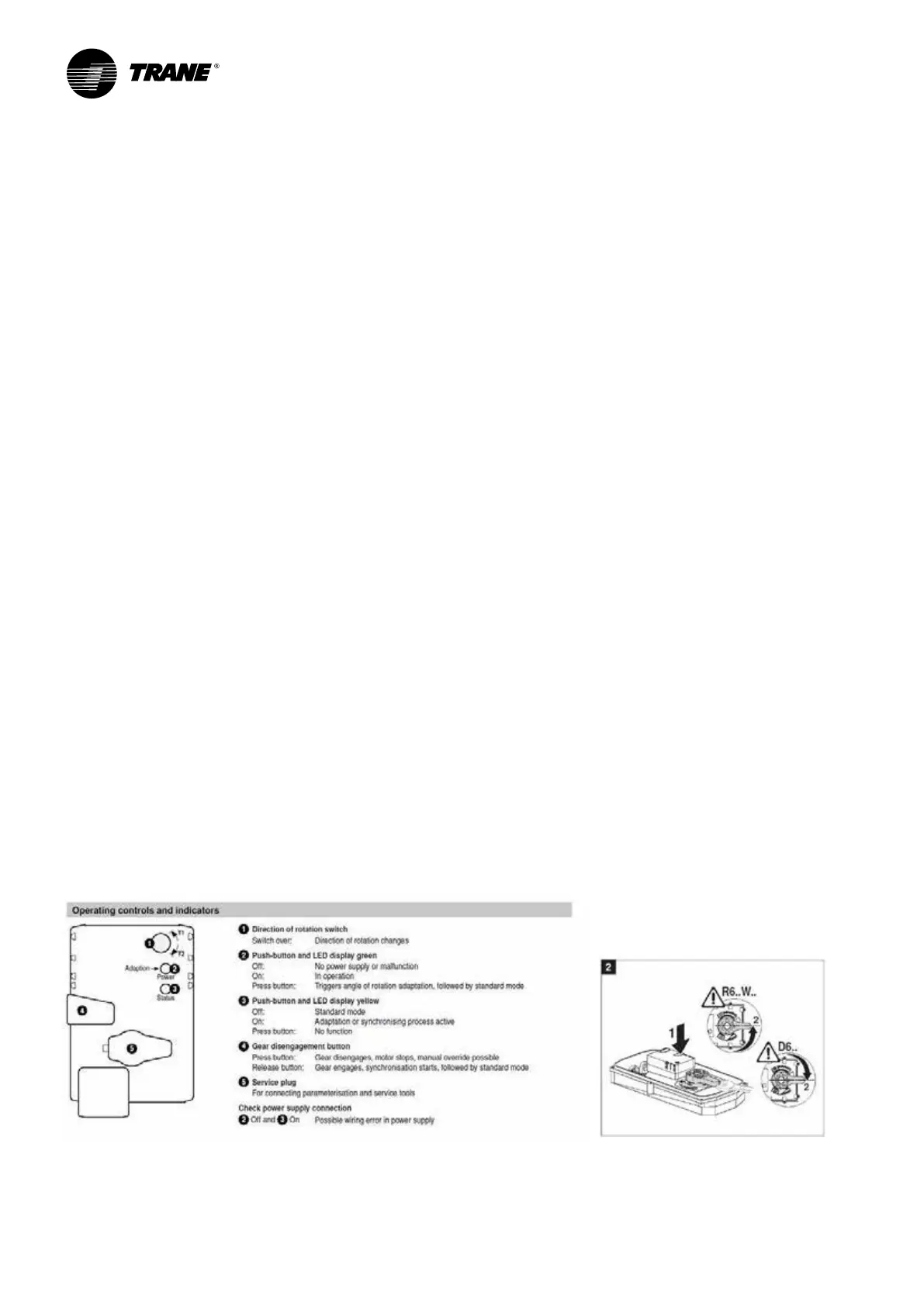
Free cooler by-pass valve adjustment
For intervention on free cooler by-pass valve it is
recommended to consult the valve service literature.
For every new referencing of the motor end travel, an
adaptation of the motor should be done by pushing
button 2.
To change the bypass percentage follows below
procedure:
− No tuning is needed on free cooling valve which
always stays on full opening/closure.
− For bypass valve Belimo, minimum opening
can be adjusted by pushing the release button
(4) and by turning handle 5 to 50% opening for
instance (45°)

 Loading...
