RLC-SVX19G-GB
99
11UNT-PRC002-GB
Sound power levels
Discharge
Measurement conditions:
Measurements taken in a room adjacent to the room containing the FWD, at the outlet of the rectangular duct (1.5 m
long) fixed to its discharge opening.
Fan Power level in dB(A), per Hz frequency band Overall power
Unit speed 125 250 500 1000 2000 4000 8000 dB(A)
1 55 50 42 37 37 31 30 46
FWD 08 2 57 54 47 40 30 38 40 50
3 58 57 50 42 32 40 43 53
1 57 51 45 42 34 33 28 48
FWD 10 2 58 54 48 45 38 39 35 51
3 60 58 50 48 40 42 39 54
1 57 51 45 42 34 33 28 48
FWD 12 2 58 54 48 45 38 39 35 51
3 60 58 50 48 40 42 39 54
1 56 62 50 48 39 38 36 56
FWD 14 2 61 66 55 53 47 46 45 60
3 63 69 58 56 50 50 49 63
1 57 63 51 49 40 39 37 57
FWD 20 2 61 66 55 53 47 46 45 60
3 63 69 58 56 50 50 49 63
Intake
Measurement conditions:
Measurements taken at the horizontal air intake.
Fan Power level in dB(A), per Hz frequency band Overall power
Unit speed 125 250 500 1000 2000 4000 8000 dB(A)
1 56 55 55 53 46 45 42 57
FWD 08 2 63 62 60 60 53 53 53 64
3 66 65 63 62 56 55 57 67
1 62 58 55 58 51 48 44 61
FWD 10 2 66 63 60 62 56 55 52 66
3 70 67 63 65 59 59 57 69
1 62 58 55 58 51 48 44 61
FWD 12 2 66 63 60 62 56 55 52 66
3 70 67 63 65 59 59 57 69
1 66 65 65 65 57 50 46 68
FWD 14 2 73 72 69 71 64 59 57 74
3 78 76 73 75 69 64 63 78
1 68 72 64 64 56 52 50 69
FWD 20 2 76 76 68 71 65 61 61 75
3 78 79 71 74 69 66 66 78
Installation Requirements
Elastomeric Isolators Installation
(Optional)
Isolators are ready to install. Mountings have to
be placed on a rigid and level foundation. External
equipment should not transmit additional vibration to
the chiller. The position of elastomeric isolator and
weight per point are given in the Neoprene isolators
installation drawing which is supplied with the chiller.
Wrong placement along the unit may result in excessive
deflection.
1. Secure the isolators to the mounting surface
using the mounting slots in the isolator’s base
plate. Do NOT fully tighten the isolators mounting
bolts at this time. See the isolators submittals for
isolators location, maximum weights, and isolators
diagrams.
2. Align the mounting holes in the base of the unit
with the threaded positioning pins on the top of the
isolators.
3. Install the unit on the isolators and secure the
isolators to the unit with a nut. The maximum
isolators deflection should be 13 mm.
4. Level the unit carefully. Fully tighten the isolator
mounting bolts.
Figure 1 – Elastomeric Isolator
14.2
127
16
63.5
70
12.7
40.6
Isolator Pads Installation (Optional)
Isolators are ready to install. Mountings have to
be placed on a rigid and level foundation. External
equipment should not transmit additional vibration to
the chiller. The position of pads isolator is given in the
pad isolators installation or selection drawing which is
supplied with the chiller.
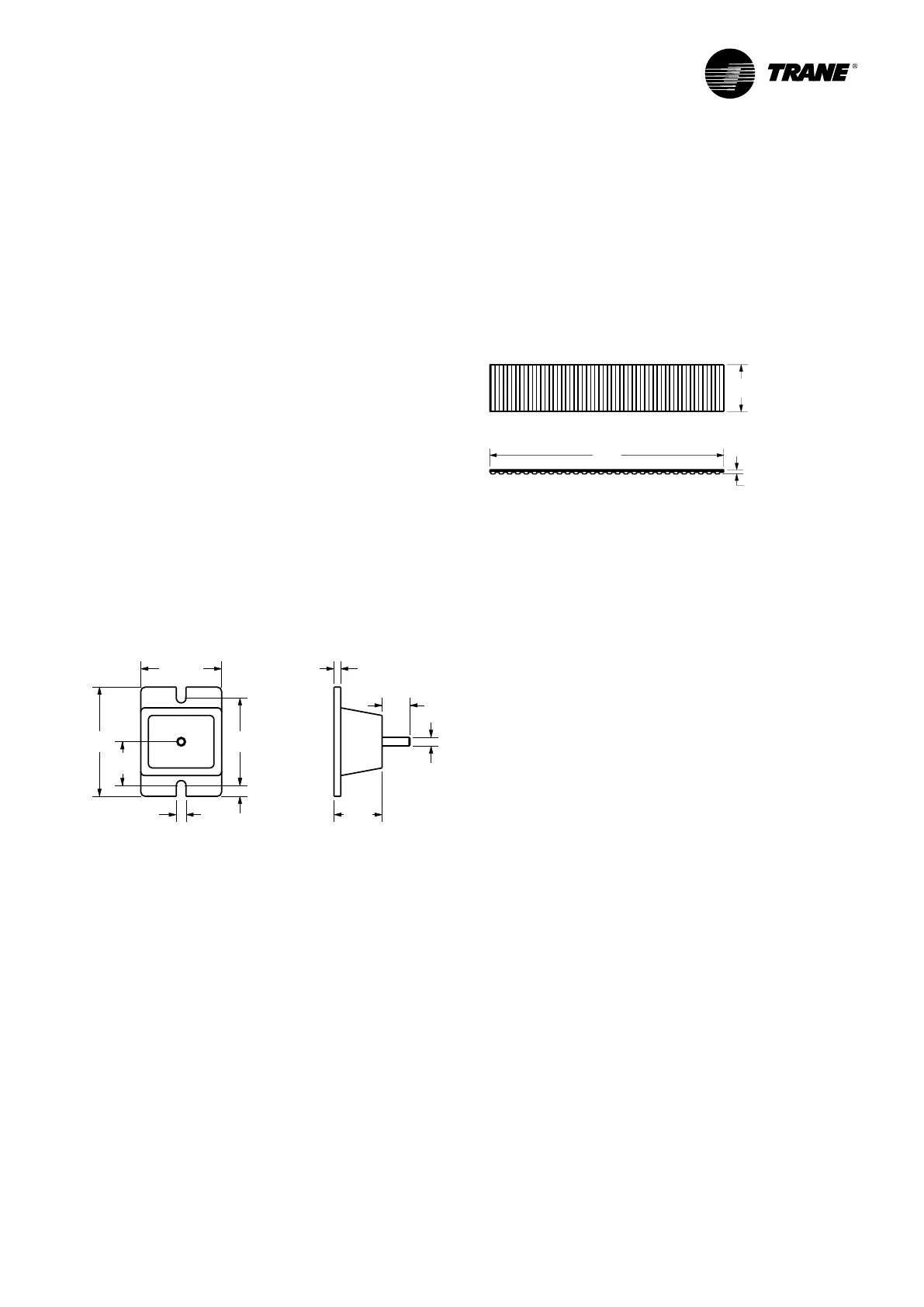
Figure 2 – Isolator pads
450
90
8
1
2
3
4
5
6
7
8
RTAF 190 HE_190 XE_190 HSE_205 HE_205 XE_205 HSE
1
2
3
4
5
6
RTAF 090_105_125_145_155_175

 Loading...
