Chapter 8 Installing the circuit board
54 CNT-SVN01C-EN
4. Connect the 60-pin cable to the 60-pin slot, then connect the 20-pin
cable to the 20-pin slot (see Figure 33 on page 53).
The connectors fit only one way. If you have difficulty connecting
them, make sure that the plastic grooves line up with the slots.
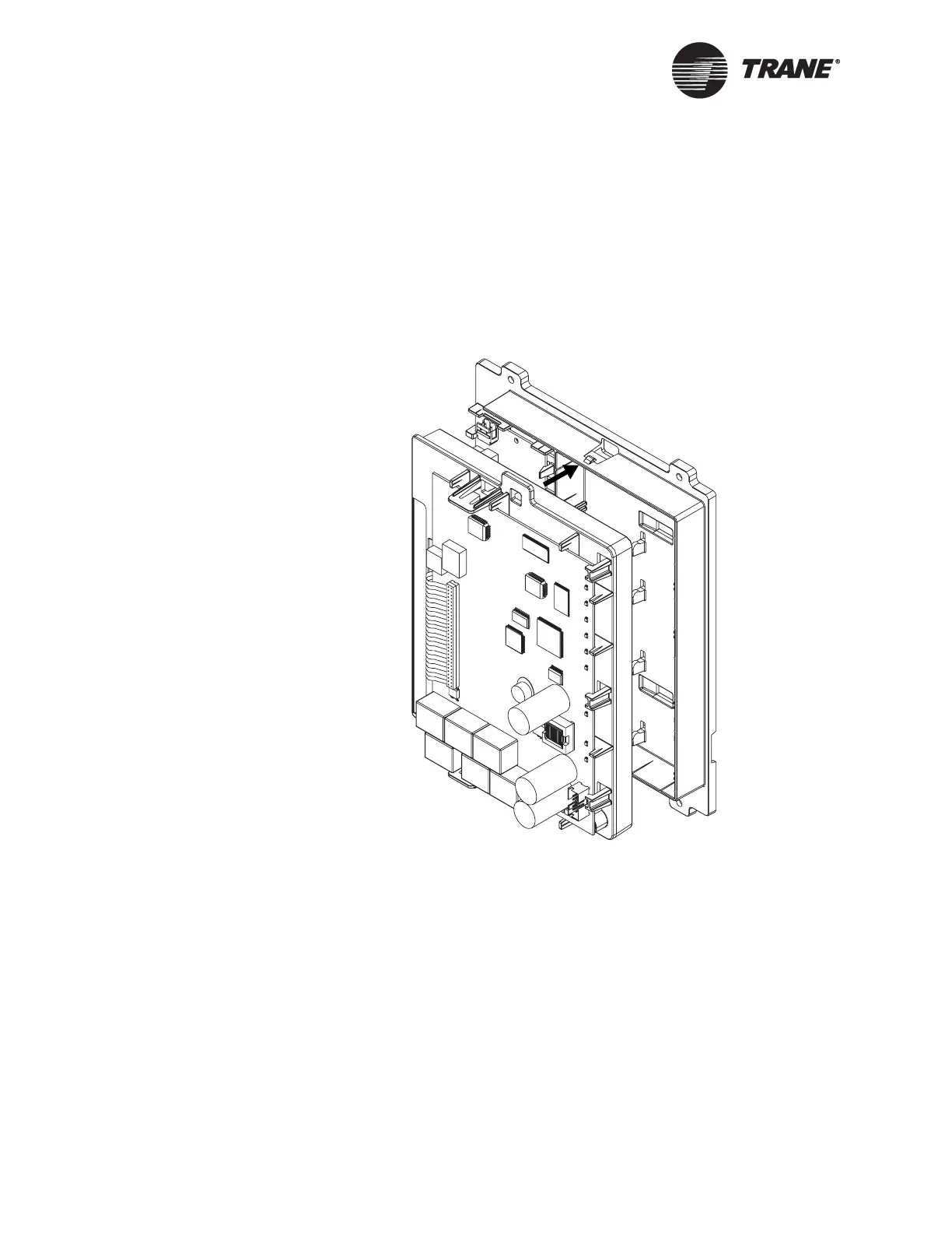
5. Align the snaps on the top frame with the mounting locks on the bot-
tom frame, as shown in Figure 34, then push the two frames together.
You will hear a click when the frames connect.
Figure 34. Connecting the frames
6. For controllers with an operator display, connect the operator-display
cable to the circuit board (see Figure 35 on page 55).
7. Locate the 24 Vac power connector on the termination board (see
Figure 35). Remove the mating plug with screw terminals.
8. Attach the 24 Vac power-supply cable to the screw terminals on the
mating plug.
9. Connect the mating plug to the 24 Vac power connector on the termi-
nation board. The green status LED should light up.
10. Check status LEDs according to Chapter 14, “Verifying operation and
communication.”

 Loading...


