11 6 UNT-SVX07B-EN
Diagnostics
Diagnostics
LED1, LED2, and LED3, located on the sensor of model WTS respond to diagnostics by exhibiting
specific blinking patterns. View their response by pressing the Test button (see Table 38).
Error codes appear on the display of the model WDS sensor when diagnostics occur (see Table 38).
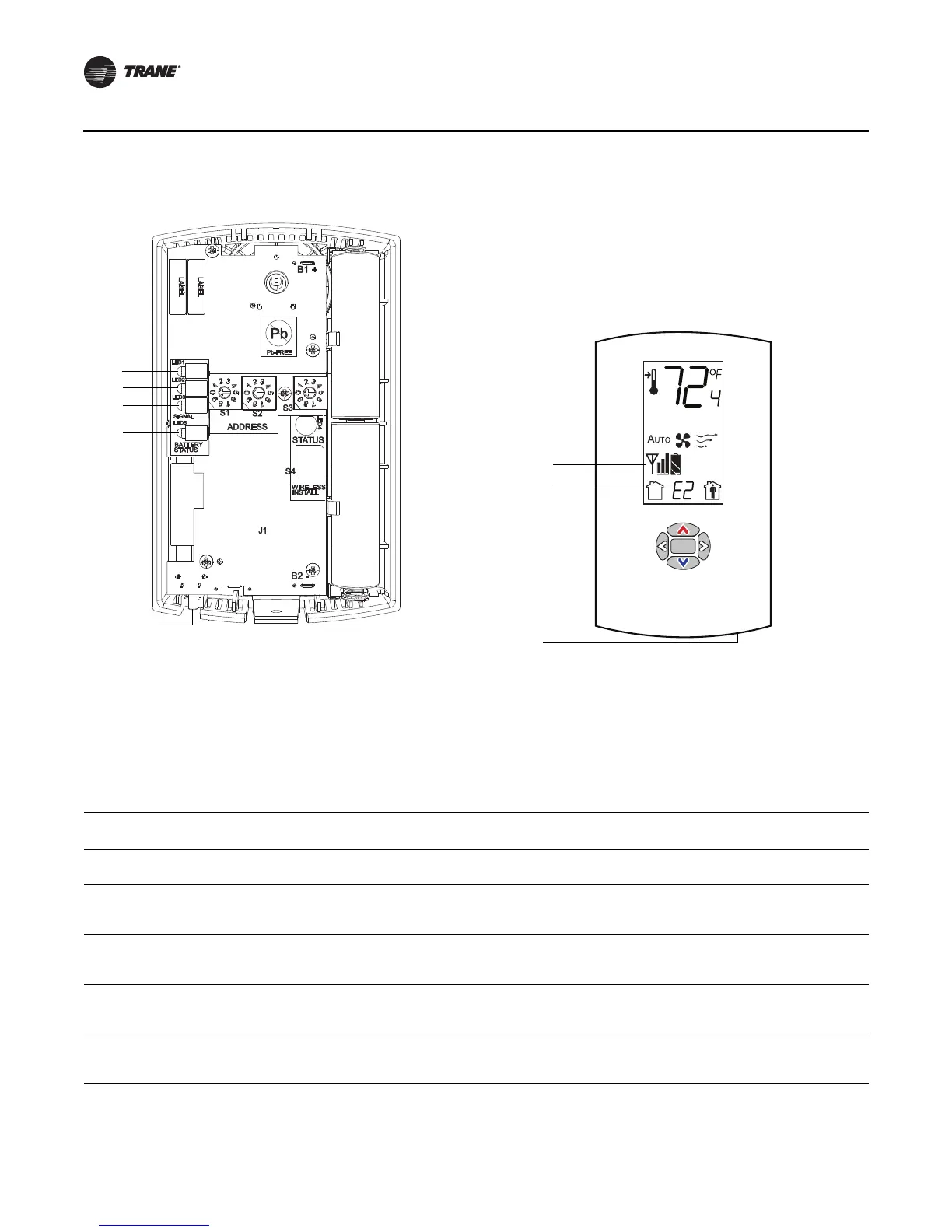
Figure 31. LED, Test button, and symbol locations on the sensor
.
Test symbols
Error code
Test button
LED1
LED2
LED3
LED5
Test button
WTS sensor WDS sensor
Table 38. Diagnostics on the sensor
LED state when Test button is pressed
(WTS sensor)
Error code (WDS
sensor display) Indicates...
N/A E0, E5, E7 Sensor failure
• Replace sensor
LED1: Off
LED2: Off
LED3
(a)
: 1-blink pattern repeated 3 times
E1 Disassociated
• Sensor is not associated with a receiver.
LED1: Off
LED2: Off
LED3
(a)
: 2-blink pattern repeated 3 times
E2 Address set to 000
• Address not set to between 001–999.
LED1: Off
LED2: Off
LED3
(a)
: 3-blink pattern repeated 3 times
E3 Software error
• Replace sensor
LED1: Off
LED2: Off
LED3
(a)
: 4-blink pattern repeated 3 times
E4 Input voltage too high
• No RF transmission is permitted with an input battery voltage
greater than 3.9 V.
(a) Blink pattern is On for 1/4 s, Off for 1/4 s, with 2 s Off between repetitions.

 Loading...


