Commander Installation Guide
Page 44 of 81 Trilogy Communications Limited
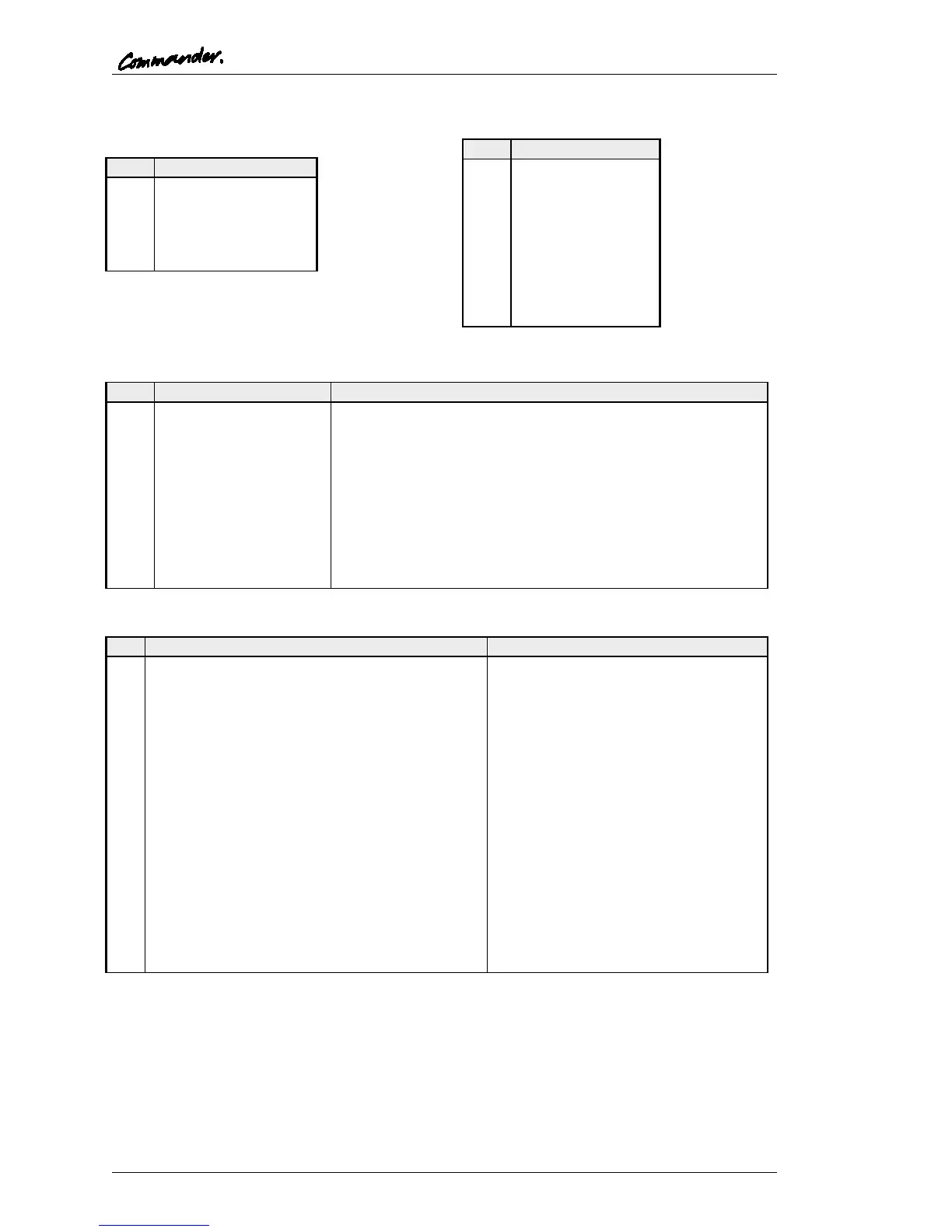
Headset - 5 Pin XLR Fixed Socket (front
panel)
Foot Switch - D9 Fixed Socket
GPIO (Local logic in and out) - D9 Fixed Socket
Protected with series 44R & 1N4002 diode.
NB Pin 9 may be driven by external voltage (With dropper
resistor if greater than 5V), or by internal +5V via pin 5.
Audio I/O – D15 Fixed Socket
+15V Out (for slave mic panel)
Line level, balanced, pair with 11
Ext CUT Input (for slave mic panel)
Parallel function to front panel Cut
Switch. Ground to activate
External Input to LS Amp -
Line level, balanced, pair with 14
Matrix Audio Input to Panel / parallel output -
Line level, balanced, pair with 15
Ext Mic Cut output (to slave panel)
Normally grounded. O/P is open
circuit when front panel cut selected.
-15V Out (for Slave mic panel)
Line level, balanced, pair with 3
External Input to LS Amp +
Line level, balanced, pair with 7
Matrix Audio Input to Panel / parallel output +
Line level, balanced, pair with 8
NB 15V supplies are also used to derive 12V for panel. (Thermally Fused @ 0.7A)