Commander Installation Guide
Trilogy Communications Limited Page 75 of 81
8.5.6 500-39-30 / 31 1U 12 KEY PANEL WITH LOUDSPEAKER
This panel provides more basic facilities than the 500-30 range. It does not have LCD
displays and only provides connection to the matrix, audio I/O and the test port at the rear.
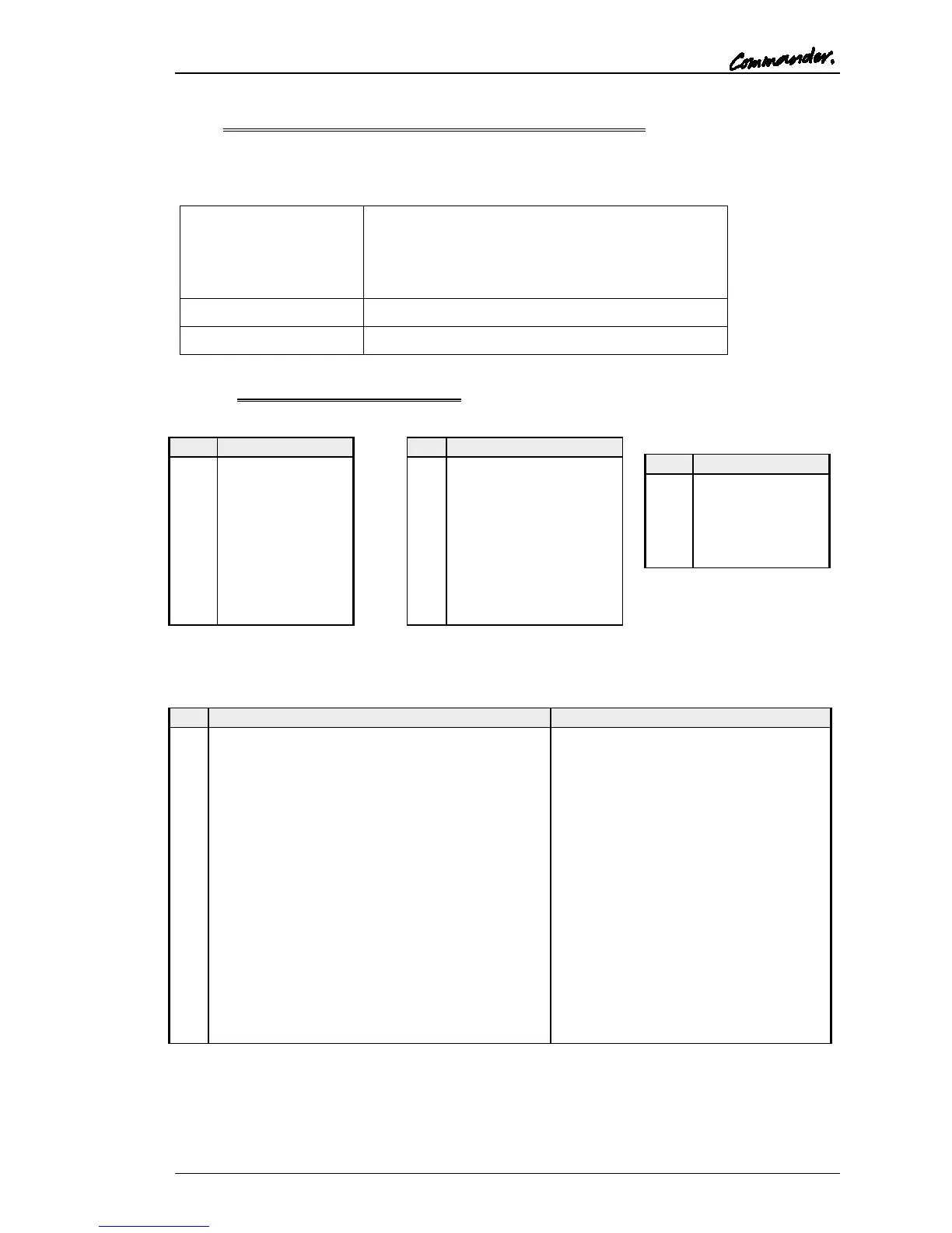
An installation specification is given below.
485mm wide x 44.5mm high x 150mm deep
(excluding connectors) 200m approx. (including
mating connectors)
19” x 1RU rack mounting
150mA @ 90V ac, 50mA @ 250V ac.
8.5.6.1 500-39-30 Connector Pin Out
Matrix – D9 Fixed Plug
Headset - 5 Pin XLR Fixed
Socket (front panel)
Audio I/O – D15 Fixed Socket
+15V Out (for slave mic panel)
Line level, balanced, pair with 11
Ext CUT Input (for slave mic panel)
Parallel function to front panel Cut
Switch. Ground to activate
External Input to LS Amp -
Line level, balanced, pair with 14
Matrix Audio Input to Panel / parallel output -
Line level, balanced, pair with 15
Ext Mic Cut output (to slave panel)
Normally grounded. O/P is open
circuit when front panel cut selected.
-15V Out (for Slave mic panel)
Line level, balanced, pair with 3
External Input to LS Amp +
Line level, balanced, pair with 7
Matrix Audio Input to Panel / parallel output +
Line level, balanced, pair with 8
NB 15V supplies are also used to derive 12V for panel. (Thermally Fused @ 0.7A)
The 500-39-31 panel includes an additional expansion connector, logic GPIO signals and
footswitch connector in the same format as the 500-3x-3x series expansion panels. It is only
available to special order. See section 8.5.2.2 for connector details.