APPLICATION
ADJUSTMENTS
REQUIRED
BEFORE
STARTING
MEASUREMENTS
PROBE
COMPENSATION
If accurate measurements are to be made, the effect of the
probe being used must be properly adjusted output of the
measurement system using the internal calibration signal or
some other squarewave source.
1.
Connect the probe to the channel to be used and set the
various controls for a normal A sweep display.
2.
Adjust the SWEEP TIME/DIV control display of several
cycles of the signal from the calibration output, CAL,
terminal.
3. Adjust the probe compensation control for a proper
waveform display.
4.
The other channels are compensated for in the same
way. Note that for CH3 and CH4 the sensitivity is
0.1V/DIV (1/1) so that when using a 10:1 probe
sufficient waveform amplitude is not available, so that
an alternate squarewave signal generator must be used
for the compensating procedure.
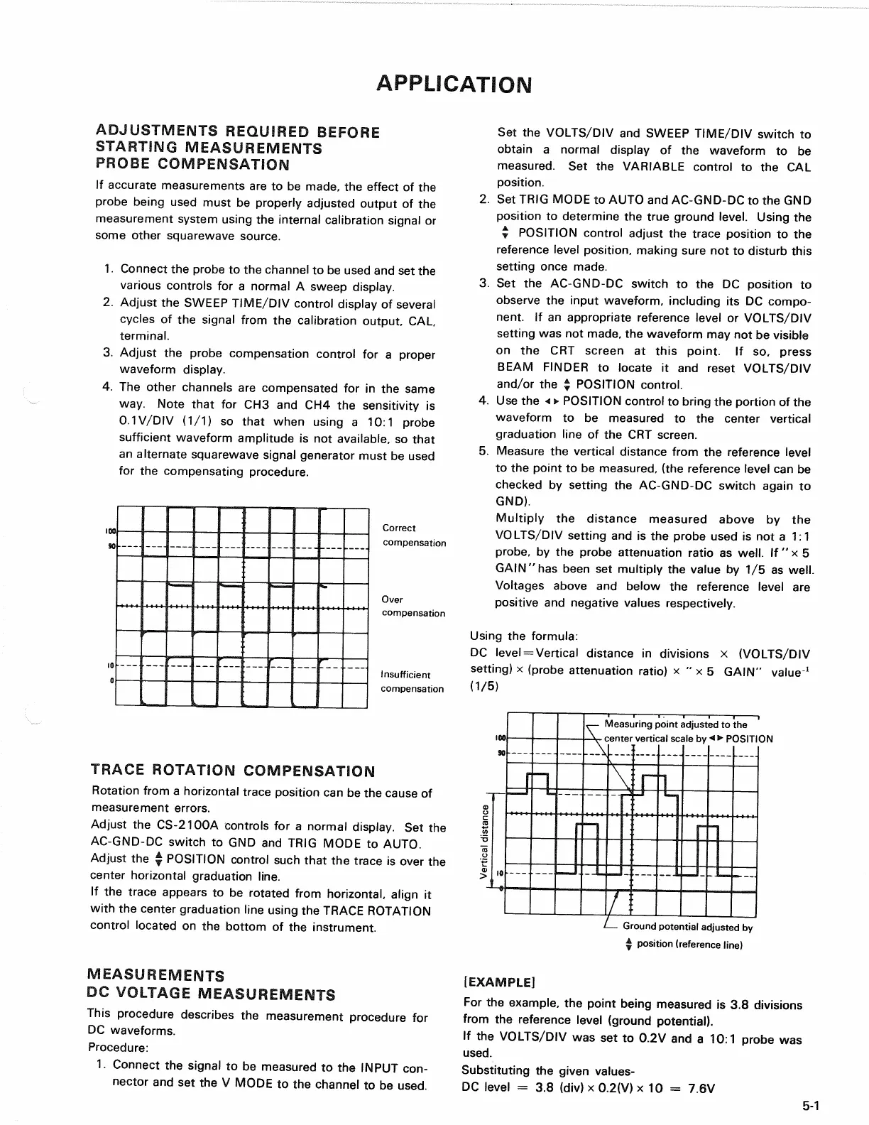
Correct
compensation
Over
compensation
Insufficient
compensation
TRACE
ROTATION COMPENSATION
Rotation from a horizontal trace position can be the cause of
measurement errors.
Adjust the CS-2100A controls for a normal display. Set the
AC-GND-DC switch to GND and TRIG MODE to AUTO.
Adjust the * POSITION control such that the trace is over the
center horizontal graduation line.
If the trace appears to be rotated from horizontal, align it
with the center graduation line using the TRACE ROTATION
control located on the bottom of the instrument.
MEASUREMENTS
DC
VOLTAGE MEASUREMENTS
This procedure describes the measurement procedure for
DC waveforms.
Procedure:
1.
Connect the signal to be measured to the INPUT
con-
nector and set the V MODE to the channel to be used.
Set the VOLTS/DIV and SWEEP TIME/DIV switch to
obtain a normal display of the waveform to be
measured.
Set the VARIABLE control to the CAL
position.
2.
Set TRIG MODE to AUTO and AC-GND-DC to the GND
position to determine the true ground level. Using the
T
POSITION control adjust the trace position to the
reference level position, making sure not to disturb this
setting once made.
3. Set the AC-GND-DC switch to the DC position to
observe the input waveform, including its DC compo-
nent. If an appropriate reference level or VOLTS/DIV
setting was not made, the waveform may not be visible
on the CRT screen at this point. If so, press
BEAM FINDER to locate it and reset VOLTS/DIV
and/or the | POSITION control.
4.
Use the « • POSITION control to bring the portion of the
waveform to be measured to the center vertical
graduation line of the CRT screen.
5. Measure the vertical distance from the reference level
to the point to be measured, (the reference level can be
checked by setting the AC-GND-DC switch again to
GND).
Multiply the distance measured above by the
VOLTS/DIV setting and is the probe used is not a 1:1
probe,
by the probe attenuation ratio as
well.
If " x 5
GAIN"has been set multiply the value by 1/5 as
well.
Voltages above and below the reference level are
positive and negative values respectively.
Using the formula:
DC level = Vertical distance in divisions x (VOLTS/DIV
setting) x (probe attenuation ratio) x " x 5 GAIN" value
1
(1/5)
Measuring point adjusted to the
center vertical scale
by<>
POSITION
5-1
Ground potential adjusted by
y
position (reference line)
[EXAMPLE]
For the example, the point being measured is 3.8 divisions
from the reference level (ground potential).
If the VOLTS/DIV was set to 0.2V and a 10:1 probe was
used.
Substituting the given values-
DC level = 3.8 (div) x 0.2(V) x 10 = 7.6V