SPECIFICATIONS
A Sweep time: 20ns/div
to
0.5s/div
in 23
ranges,
in
1
-2-5
sequence,
verninier control provides
fully adjustable sweep time
between steps.
B Sweep time: 20ns/div
to
50ms/div
in 20
ranges,
in
1
-2-5
sequence.
Accuracy:
+3% (10 ~
35°C)
±6%(0 ~50°C)
Sweep magnification:
X10
±5%
(10 ~
35°C)
±7%
(0 ~
50°C)
Linearity: 20ns/div
to
0.5s/div
±3%
(±5%
with
X10
magnification)
HOLDOFF: Continuously adjustable
for A
Sweep hold
off
time from
NORM
to X5.
Trace separation:
B
positionable
up to 4
divisions separated from
A
Sweep, continuously adjustable.
Delay method: Continuous delay. SYNC delay
Delay time:
0.2 to 10
times
the
sweep time
from 200ns
to
0.5s,
continu-
ously adjustable.
Time difference measurement accuracy:
±2%
(10
~ 35 °C)
±4%(0
~
50°C)
Delay jitter:
1
/20000
of
the
full scale
sweep time.
TRIGGERING
ATRIG
A trigger modes: AUTO. NORM, SINGLE,
FIX:
at
the
center
of
the
waveform
Trigger source:
V
MODE.
CH 1, CH2. (EXT)
CH3
1/1 and
1/10
Coupling modes:
AC,
LF
REJ
,
HF
REJ
,
DC,
VIDEO
VIDEO-LINE sync automatically
selected
at
sweep times
of
50 yus/div
to
20ns/div.
VIDEO-FRAME sync automatically
selected
at
sweep times
of 0.5s/div
to
0.1
ms/div.
Trigger level: ±90° adjustable
Polarity:
+/
—
B TRIG
B trigger modes STARTS AFTER DELAY,
TRIGGERABLE AFTER DELAY
Trigger source:
CH 1, CH2, (EXT) CH4
1/1 and
1/10
Coupling
modes: AC,
LFREJ,
HFREJ,
DC
Trigger level: ±90° adjustable
Polarity:
+ /
—
Trigger sensitivity
(A
and
B)
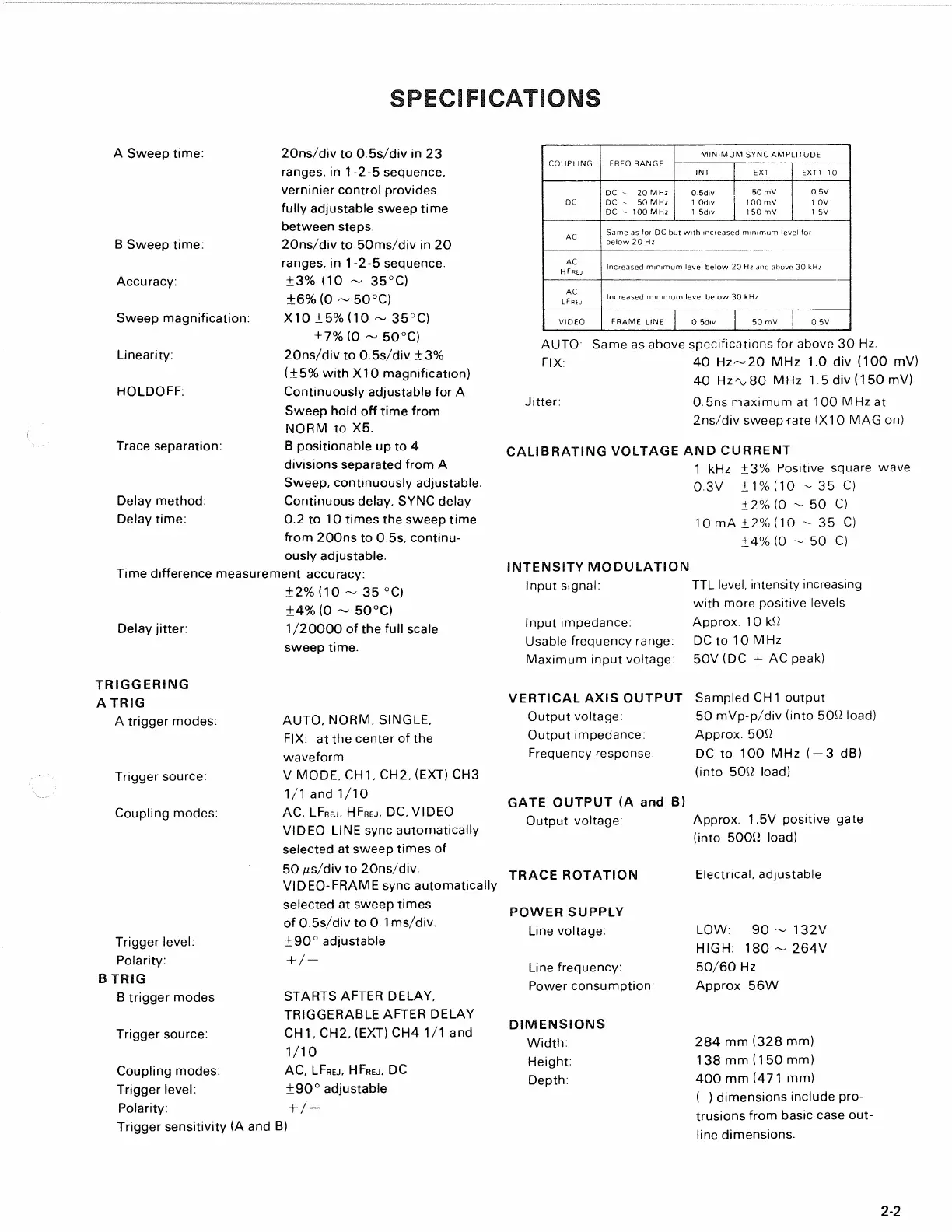
COUPLING
FREQ RANGE
MINIMUM SYNC AMPLITUDE
COUPLING
FREQ RANGE
INT EXT
EXT1
10
DC
DC
- 20
MHz
DC
- 50
MHz
DC
-
100 MHz
0 5div
1 Odiv
1 5div
50 mV
100
mV
1 50
mV
0 5V
1
OV
1
5V
AC
Same
as for DC but
with increased minimum level
for
below
20 Hz
AC
HFn[j
Increased minimum level below
20
HZ
and
above
30
KHZ
AC
LFfuj
Increased minimum level below
30 kHz
VIDEO
FRAME LINE
0 5div
50
mV
0
5V
AUTO:
Same
as
above specifications
for
above
30 Hz.
FIX:
40
Hz~20
MHz 1.0 div (100 mV)
40 Hz'vSO
MHz 1.5 div
(150
mV)
Jitter: 0.5ns maximum
at
1
00
MHz
at
2ns/div sweep rate
(X1
0
MAG
on)
CALIBRATING VOLTAGE
AND
CURRENT
1
kHz ±3%
Positive square wave
0.3V ±1%
(10
- 35 C)
+
2%
(0 - 50 C)
10mA
±2% (10
- 35 C)
±4%
(0 - 50 C)
INTENSITY MODULATION
Input signal:
TTL
level, intensity increasing
with more positive levels
Input impedance: Approx.
10 kO
Usable frequency range: DCto
10
MHz
Maximum input voltage:
50V
(DC
+ AC
peak)
VERTICAL AXIS OUTPUT Sampled
CH1
output
Output voltage:
50
mVp-p/div (into
500
load)
Output impedance: Approx.
500
Frequency response:
DC to 100 MHz (
—
3 dB)
(into
500
load)
GATE OUTPUT
(A and B)
Output voltage: Approx.
1.5V
positive gate
(into 5000 load)
TRACE ROTATION Electrical, adjustable
POWER SUPPLY
Line voltage:
LOW: 90 - 132V
HIGH:
180 ~
264V
Line frequency. 50/60
Hz
Power consumption: Approx.
56W
DIMENSIONS
Width:
284 mm
(328
mm)
Height:
138 mm
(150
mm)
Depth:
400 mm
(471mm)
(
)
dimensions include pro-
trusions from basic case out-
line dimensions.
2-2