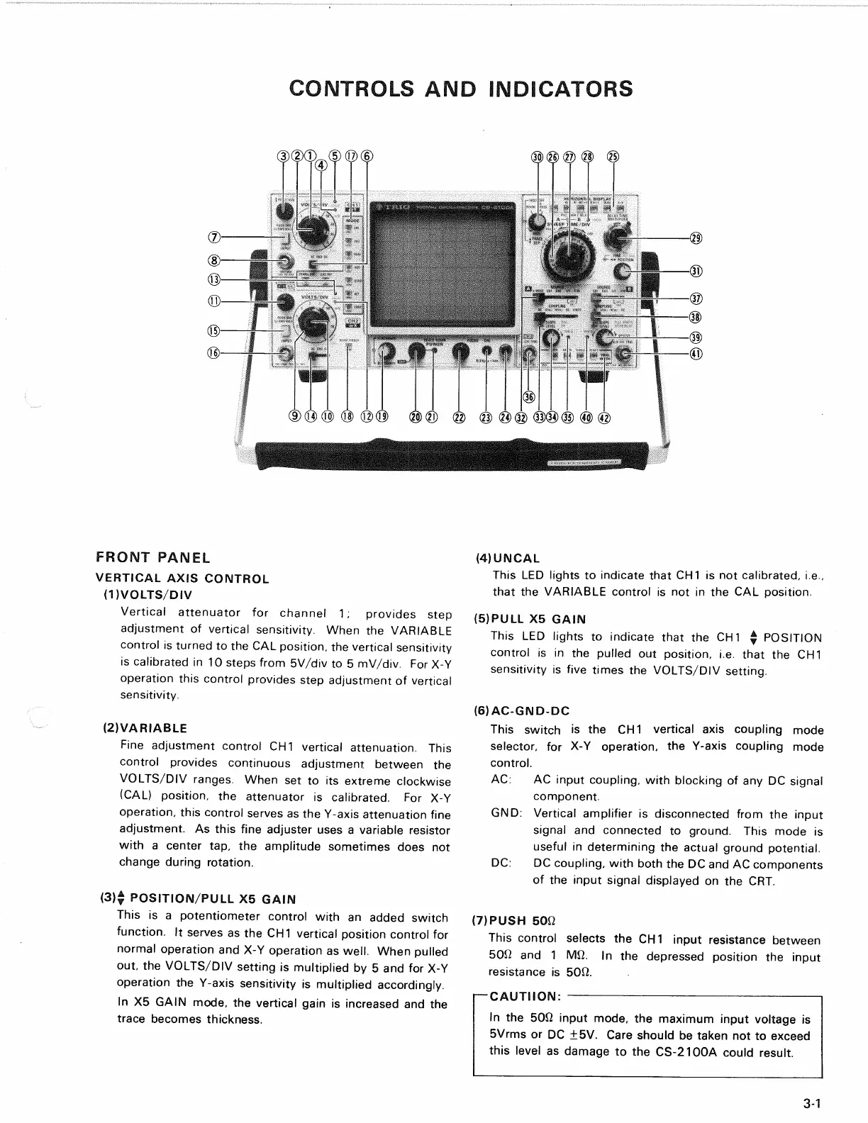
CONTROLS AND INDICATORS
FRONT PANEL
VERTICAL AXIS CONTROL
(DVOLTS/DIV
Vertical attenuator for channel 1; provides step
adjustment of vertical sensitivity. When the VARIABLE
control is turned to the CAL position, the vertical sensitivity
is calibrated in 10 steps from 5V/div to 5 mV/div. For X-Y
operation this control provides step adjustment of vertical
sensitivity.
(2) VARIABLE
Fine adjustment control CH1 vertical attenuation. This
control provides continuous adjustment between the
VOLTS/DIV ranges. When set to its extreme clockwise
(CAL) position, the attenuator is calibrated. For X-Y
operation,
this control serves as the Y-axis attenuation fine
adjustment. As this fine adjuster uses a variable resistor
with a center tap, the amplitude sometimes does not
change during rotation.
(3) $ POSITION/PULL X5 GAIN
This is a potentiometer control with an added switch
function.
It serves as the CH1 vertical position control for
normal operation and X-Y operation as
well.
When pulled
out, the VOLTS/DIV setting is multiplied by 5 and for X-Y
operation the Y-axis sensitivity is multiplied accordingly.
In X5 GAIN mode, the vertical gain is increased and the
trace becomes thickness.
(4) UNCAL
This LED lights to indicate that CH1 is not calibrated, i.e.,
that the VARIABLE control is not in the CAL position.
(5) PULL X5 GAIN
This LED lights to indicate that the CH1 $ POSITION
control is in the pulled out position, i.e. that the CH1
sensitivity is five times the VOLTS/DIV setting.
(6) AC-GND-DC
This switch is the CH1 vertical axis coupling mode
selector, for X-Y operation, the Y-axis coupling mode
control.
AC:
AC input coupling, with blocking of any DC signal
component.
GND:
Vertical amplifier is disconnected from the input
signal and connected to ground. This mode is
useful in determining the actual ground potential.
DC:
DC coupling, with both the DC and AC components
of the input signal displayed on the CRT.
(7) PUSH 5012
This control selects the CH1 input resistance between
50i2 and 1 Mfi. In the depressed position the input
resistance is 5012.
I—CAUTIION:
In the 50Q input mode, the maximum input voltage is
5Vrms or DC ±5V. Care should be taken not to exceed
this level as damage to the CS-2100A could result.
3-1