APPLICATION
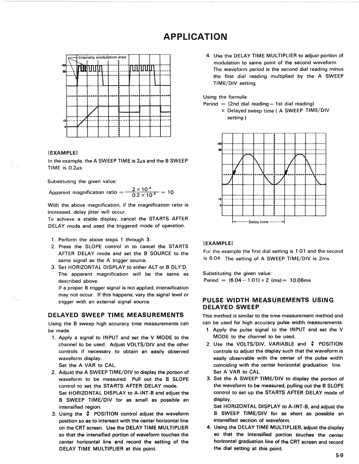
[EXAMPLE]
In
the
example,
the A
SWEEP TIME
is
2fis
and the B
SWEEP
TIME
is
0.2MS.
Substituting
the
given value:
2
x 10"
6
Apparent magnification ratio
=—.
0
^ . _
6
= 10
With
the
above magnification,
if the
magnification ratio
is
increased,
delay jitter will occur.
To achieve
a
stable display, cancel
the
STARTS AFTER
DELAY mode
and
used
the
triggered mode
of
operation.
4.
Use the
DELAY TIME MULTIPLIER
to
adjust portion
of
modulation
to
same point
of the
second weveform
The waveform period
is the
second dial reading minus
the first dial reading multiplied
by the A
SWEEP
TIME/DIV setting.
Using
the
formula:
Period
= (2nd
dial reading—1st dial reading)
x Delayed sweep time
( A
SWEEP TIME/DIV
setting
)
Delay time
1.
Perform
the
above steps
1
through
3.
2.
Press
the
SLOPE control
in to
cancel
the
STARTS
AFTER DELAY mode
and set the B
SOURCE
to the
same signal
as the A
trigger source.
3.
Set
HORIZONTAL DISPLAY
to
either
ALT or B
DLY'D.
The apparent magnification will
be the
same
as
described above.
If
a
proper
B
trigger signal
is not
applied, intensification
may
not
occur.
If
this happens, vary
the
signal level
or
trigger with
an
external signal source.
DELAYED
SWEEP TIME MEASUREMENTS
Using
the B
sweep high accuracy time measurements
can
be made.
1.
Apply
a
signal
to
INPUT
and set the V
MODE
to the
channel
to be
used. Adjust VOLTS/DIV
and the
other
controls
if
necessary
to
obtain
an
easily observed
waveform display.
Set
the A VAR to CAL.
2.
Adjust
the A
SWEEP TIME/DIV
to
display
the
portion
of
waveform
to be
measured. Pull
out the B
SLOPE
control
to set the
STARTS AFTER DELAY mode.
Set HORIZONTAL DISPLAY
to
A-INT-B
and
adjust
the
B SWEEP TIME/DIV
for as
small
as
possible
an
intensified region.
3. Using
the •
POSITION control adjust
the
waveform
position
so as to
intersect with
the
center horizontal line
on
the CRT
screen.
Use the
DELAY TIME MULTIPLIER
so that
the
intensified portion
of
waveform touches
the
center horizontal line
and
record
the
setting
of the
DELAY TIME MULTIPLIER
at
this point.
(EXAMPLE]
For
the
example
the
first dial setting
is 1.01 and the
second
is
604. The
setting
of A
SWEEP TIME/DIV
is 2ms.
Substituting
the
given value:
Period
=
(6.04-1.01)
x 2
(ms)
=
10.06ms
PULSE
WIDTH MEASUREMENTS USING
DELAYED
SWEEP
This method
is
similar
to the
time measurement method
and
can
be
used
for
high accuracy pulse width measurements.
1.
Apply
the
pulse signal
to the
INPUT
and set the V
MODE
to the
channel
to be
used.
2.
Use the
VOLTS/DIV, VARIABLE
and %
POSITION
controls
to
adjust
the
display such that
the
waveform
is
easily observable with
the
center
of the
pulse width
coinciding with
the
center horizontal graduation line.
Set
A VAR to CAL.
3.
Set the A
SWEEP TIME/DIV
to
display
the
portion
of
the waveform
to be
measured, pulling
out the B
SLOPE
control
to set up the
STARTS AFTER DELAY mode
of
display.
Set HORIZONTAL DISPLAY
to
A-INT-B,
and
adjust
the
B SWEEP TIME/DIV
for as
short
as
possible
an
intensified section
of
waveform.
4.
Using
the
DELAY TIME MULTIPLIER, adjust
the
display
so that
the
intensified portion touches
the
center
horizontal graduation line
of the CRT
screen
and
record
the dial setting
at
this point.
5-9
-Intensity modulation area