APPLICATION
SWEEP MULTIPLICATION
(MAGNIFICATION)
The apparent magnification of the delayed sweep is determi-
ned by the values set by the A and B SWEEP TIME/DIV
controls
1.
Apply a signal to the INPUT and set the V MODE to the
channel to be used, adjusting VOLTS/DIV for an easily
observed display of the waveform and the other controls
if necessary.
2.
Set the A SWEEP TIME/DIV so that several cycles of
the waveform are displayed. Set the B SLOPE to
STARTS AFTER DELAY (pull out).
When HORIZONTAL DISPLAY is set to A-INT-B, the
magnified portion of the waveform will appeared
intensified on the CRT display.
3. Use the DELAY TIME MULTIPLIER to shift the
intensified portion of waveform to correspond with the
section to be magnified for observation. Use the B
SWEEP TIME/DIV to adjust intensified portion to cover
the entire portion to be magnified.
4.
Set the HORIZONTAL DISPLAY to either ALT or B
DLY'D and use the $ POSITION and * TRACE SEP
controls to adjust the display for easy viewing.
5. Time measurements are performed in the same manner
from the B sweep as was described above for A sweep
time measurements.
The apparent magnification of the intensified waveform
section is the A SWEEP TIME/DIV divided by the B
SWEEP TIME/DIV.
Using the formula:
The apparent magniffication _ A SWEEP TIME/DIV setting
of the intensified waveform ~~ B SWEEP TIME/DIV setting
5-8
Pulse
jitter'
Unknown signal
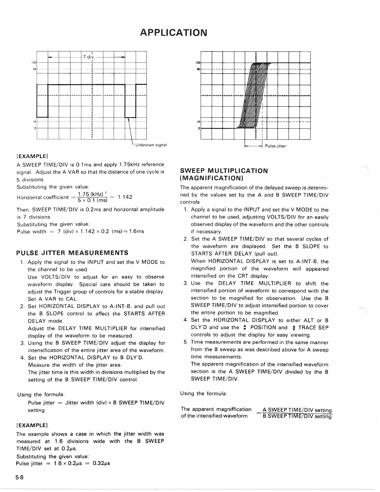
[EXAMPLE]
A SWEEP TIME/DIV is 0.1ms and apply
1.75kHz
reference
signal.
Adjust the A VAR so that the distance of one cycle is
5 divisions.
Substituting the given value:
u
• I „• •
t
1.75 (kHz)
1
. ...
Horizontal coefficient
=-=—TTT-,
r— 1.142
5 x 0.1 (ms)
Then,
SWEEP TIME/DIV is 0.2ms and horizontal amplitude
is 7 divisions.
Substituting the given value:
Pulse width = 7 (div) x 1.142 x 0.2 (ms)= 1.6ms
PULSE
JITTER
MEASUREMENTS
1.
Apply the signal to the INPUT and set the V MODE to
the channel to be used.
Use VOLTS/DIV to adjust for an easy to observe
waveform display. Special care should be taken to
adjust the Trigger group of controls for a stable display.
Set A VAR to CAL.
2.
Set HORIZONTAL DISPLAY to A-INT-B. and pull out
the B SLOPE control to affect the STARTS AFTER
DELAY mode.
Adjust the DELAY TIME MULTIPLIER for intensified
display of the waveform to be measured.
3. Using the B SWEEP TIME/DIV adjust the display for
intensification of the entire jitter area of the waveform.
4.
Set the HORIZONTAL DISPLAY to B DLY'D.
Measure the width of the jitter area.
The jitter time is this width in divisions multiplied by the
setting of the B SWEEP TIME/DIV control.
Using the formula:
Pulse jitter = Jitter width (div) x B SWEEP TIME/DIV
setting
[EXAMPLE]
The example shows a case in which the jitter width was
measured at 1.6 divisions wide with the B SWEEP
TIME/DIV set at
0.2MS.
Substituting the given value:
Pulse jitter = 1.6 x
0.2MS
=
0.32MS