APPLICATION
Adjust VOLTS/DIV and VARIABLE so that the signal
coincides with the CRT face's graduation lines. After
adjusting,
be sure not to disturb the setting of the
VARIABLE control.
2.
The vertical calibration coefficient is now the reference
signal's amplitude (in volts) divided by the product of
the vertical amplitude set in step 1 and the VOLTS/DIV
setting.
Using the formula:
Vertical coefficient
Voltage of the reference signal (V)
Vertical amplitude (div) x VOLTS/DIV setting
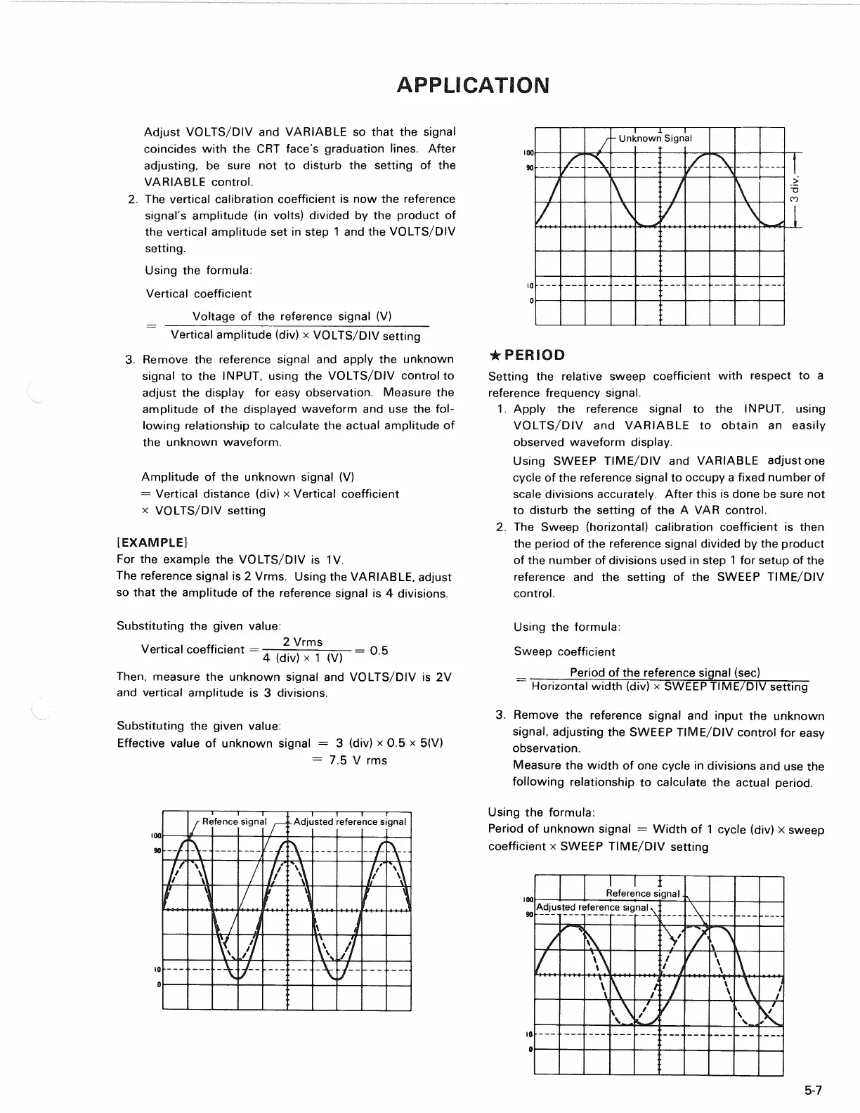
3. Remove the reference signal and apply the unknown
signal to the INPUT, using the VOLTS/DIV contralto
adjust the display for easy observation. Measure the
amplitude of the displayed waveform and use the
fol-
lowing relationship to calculate the actual amplitude of
the unknown waveform.
Amplitude of the unknown signal (V)
= Vertical distance (div) x Vertical coefficient
x VOLTS/DIV setting
[EXAMPLE]
For the example the VOLTS/DIV is 1V.
The reference signal is 2 Vrms. Using the VARIABLE, adjust
so that the amplitude of the reference signal is 4 divisions.
Substituting the given value:
Vertical coefficient =
A
, ^
VRMS
=
Q.5
4 (div) x 1 (V)
Then,
measure the unknown signal and VOLTS/DIV is 2V
and vertical amplitude is 3 divisions.
Substituting the given value:
Effective value of unknown signal = 3 (div) x 0.5 x 5(V)
= 7.5 V rms
•
PERIOD
Setting the relative sweep coefficient with respect to a
reference frequency signal.
1.
Apply the reference signal to the INPUT, using
VOLTS/DIV and VARIABLE to obtain an easily
observed waveform display.
Using SWEEP TIME/DIV and VARIABLE adjust one
cycle of the reference signal to occupy a fixed number of
scale divisions accurately. After this is done be sure not
to disturb the setting of the A VAR control.
2.
The Sweep (horizontal) calibration coefficient is then
the period of the reference signal divided by the product
of the number of divisions used in step 1 for setup of the
reference and the setting of the SWEEP TIME/DIV
control.
Using the formula:
Sweep coefficient
Period of the reference signal (sec)
~~
Horizontal width (div) x SWEEP TIME/DIV setting
3. Remove the reference signal and input the unknown
signal,
adjusting the SWEEP TIME/DIV control for easy
observation.
Measure the width of one cycle in divisions and use the
following relationship to calculate the actual period.
Using the formula:
Period of unknown signal - Width of 1 cycle (div) X sweep
coefficient x SWEEP TIME/DIV setting
5-7
Unknown Signal
Refence signal
Adjusted reference signal
Reference signal
Adjusted reference signal