APPLICATION
• Read the dial setting when
;B sweep points of DELAY
TIME MULTIPLIER © and
_(2) are in the same position.
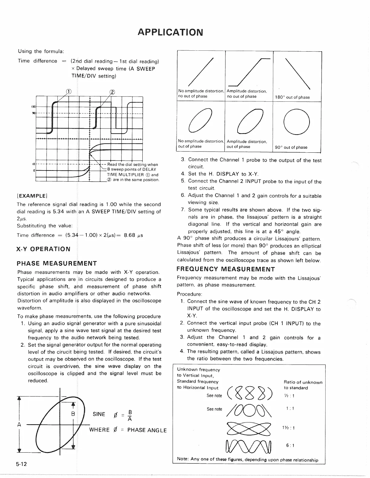
[EXAMPLE]
The reference signal dial reading is 1.00 while the second
dial reading is 5.34 with an A SWEEP TIME/DIV setting of
2/is.
Substituting the value:
Time difference = (5.34—1.00) x 2(jus) = 8.68
X-Y OPERATION
PHASE MEASUREMENT
Phase measurements may be made with X-Y operation.
Typical applications are in circuits designed to produce a
specific phase shift, and measurement of phase shift
distortion in audio amplifiers or other audio networks.
Distortion of amplitude is also displayed in the oscilloscope
waveform.
To make phase measurements, use the following procedure
1.
Using an audio signal generator with a pure sinusoidal
signal,
apply a sine wave test signal at the desired test
frequency to the audio network being tested.
2.
Set the signal generator output for the normal operating
level of the cirucit being tested. If desired, the circuit's
output may be observed on the oscilloscope. If the test
circuit is overdriven, the sine wave display on the
oscilloscope is clipped and the signal level must be
reduced.
SINE
of = i
P
A
WHERE 0 = PHASE ANGLE
3. Connect the Channel 1 probe to the output of the test
circuit.
4.
Set the H. DISPLAY to X-Y.
5. Connect the Channel 2 INPUT probe to the input of the
test circuit.
6. Adjust the Channel 1 and 2 gain controls for a suitable
viewing size.
7. Some typical results are shown above. If the two
sig-
nals are in phase, the lissajous' pettern is a straight
diagonal line. If the vertical and horizontal gain are
properly adjusted, this line is at a 45° angle.
A 90° phase shift produces a circuilar Lissajours' pattern.
Phase shift of less (or more) than 90° produces an elliptical
Lissajous' pattern. The amount of phase shift can be
calculated from the oscilloscope trace as shown left below.
FREQUENCY MEASUREMENT
Frequency measurement may be mode with the Lissajous'
pattern,
as phase measurement.
Procedure:
1.
Connect the sine wave of known frequency to the CH 2
INPUT of the oscilloscope and set the H. DISPLAY to
X-Y.
2.
Connect the vertical input probe (CH 1 INPUT) to the
unknown frequency.
3. Adjust the Channel 1 and 2 gain controls for a
convenient, easy-to-read display.
4.
The resulting pattern, called a Lissajous pattern, shows
the ratio between the two frequencies.
5-12
Unknown frequency
to Vertical Input,
Standard frequency
to Horizontal Input
Ratio of unknown
to standard
1V? : 1
Note: Any one of these figures, depending upon phase relationship
Using the formula:
Time difference = (2nd dial reading —
1
st dial reading)
x Delayed sweep time (A SWEEP
TIME/DIV setting)
No amplitude distortion,
no out of phase
Amplitude distortion,
no out of phase
180° out of phase
No amplitude distortion,
out of phase
Amplitude distortion,
out of phase
90° out of phase
See note
See note
Vt : 1
1 : 1
6:1