APPLICATION
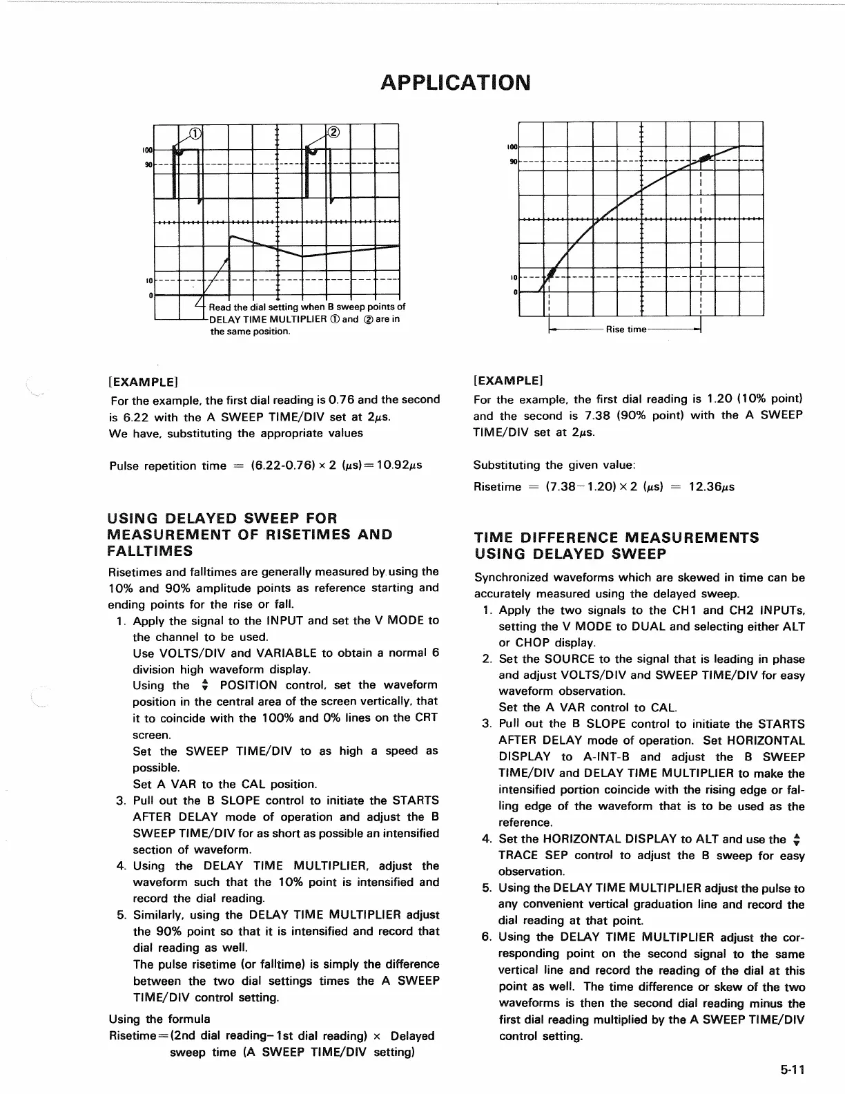
Read the dial setting when B sweep points of
DELAY TIME MULTIPLIER ® and © are in
the same position.
[EXAMPLE]
For the example, the first dial reading is 0.76 and the second
is 6.22 with the A SWEEP TIME/DIV set at 2
M
s.
We have, substituting the appropriate values
Pulse repetition time = (6.22-0.76) x 2 (MS)= 10.92/xs
USING DELAYED SWEEP FOR
MEASUREMENT OF RISETIMES AND
FALLTIMES
Risetimes and falltimes are generally measured by using the
10%
and 90% amplitude points as reference starting and
ending points for the rise or
fall.
1.
Apply the signal to the INPUT and set the V MODE to
the channel to be used.
Use VOLTS/DIV and VARIABLE to obtain a normal 6
division high waveform display.
Using the # POSITION control, set the waveform
position in the central area of the screen vertically, that
it to coincide with the 100% and 0% lines on the CRT
screen.
Set the SWEEP TIME/DIV to as high a speed as
possible.
Set A VAR to the CAL position.
3. Pull out the B SLOPE control to initiate the STARTS
AFTER DELAY mode of operation and adjust the B
SWEEP TIME/DIV for as short as possible an intensified
section of waveform.
4.
Using the DELAY TIME MULTIPLIER, adjust the
waveform such that the 10% point is intensified and
record the dial reading.
5. Similarly, using the DELAY TIME MULTIPLIER adjust
the 90% point so that it is intensified and record that
dial reading as well.
The pulse risetime (or falltime) is simply the difference
between the two dial settings times the A SWEEP
TIME/DIV control setting.
Using the formula
Risetime = (2nd dial reading- 1st dial reading) x Delayed
sweep time (A SWEEP TIME/DIV setting)
[EXAMPLE]
For the example, the first dial reading is 1.20 (10% point)
and the second is 7.38 (90% point) with the A SWEEP
TIME/DIV set at 2/is.
Substituting the given value:
Risetime = (7.38-1.20) x 2 (us) =
12.36MS
TIME DIFFERENCE MEASUREMENTS
USING DELAYED SWEEP
Synchronized waveforms which are skewed in time can be
accurately measured using the delayed sweep.
1.
Apply the two signals to the CH1 and CH2 INPUTS,
setting the V MODE to DUAL and selecting either ALT
or CHOP display.
2.
Set the SOURCE to the signal that is leading in phase
and adjust VOLTS/DIV and SWEEP TIME/DIV for easy
waveform observation.
Set the A VAR control to CAL.
3. Pull out the B SLOPE control to initiate the STARTS
AFTER DELAY mode of operation. Set HORIZONTAL
DISPLAY to A-INT-B and adjust the B SWEEP
TIME/DIV and DELAY TIME MULTIPLIER to make the
intensified portion coincide with the rising edge or
fal-
ling edge of the waveform that is to be used as the
reference.
4.
Set the HORIZONTAL DISPLAY to ALT and use the *
TRACE SEP control to adjust the B sweep for easy
observation.
5. Using the DELAY TIME MULTIPLIER adjust the pulse to
any convenient vertical graduation line and record the
dial reading at that point.
6. Using the DELAY TIME MULTIPLIER adjust the cor-
responding point on the second signal to the same
vertical line and record the reading of the dial at this
point as well. The time difference or skew of the two
waveforms is then the second dial reading minus the
first dial reading multiplied by the A SWEEP TIME/DIV
control setting.
5-11
Rise time