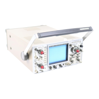
CONTROLS AND INDICATORS
(8) INPUT
CH1 vertical input connector; serves also as the Y-axis
input connector for X-Y operation.
(9) VOLTS/DSV
Vertical attenuator for channel 2; provides step
adjustment of vertical sensitivity, VARIABLE control is tur-
ned to the CAL position, the vertical sensitivity calibrated
in 10 steps from 5V/div to 5 mV/div. For X-Y operation
the control provides step adjustment of horizontal
sensitivity.
(10) VARIABLE
CH2 vertical attenuation fine adjustment. Operation is
similar to that of the CH
1
VARIABLE control. For X-Y
operation the control serves as the X-axis attenuation fine
adjustment.
(11) $ POSITION X-Y ^•/PULL X5
GAIN
Dual control which functions similarly to the corresponding
CH1 control. In addition, it serves as the horizontal
position control and X-axis sensitivity magnifier for X-Y
operation.
(12) UNCAL
UNCAL display for CH2 vertical axis or for the X-axis for
X-Y operation when CH2 VARIABLE control is not in CAL
position.
(13) PULL X5 GAIN
This display LED indicates that X5 magnification is in effect
for the CH2 vertical axis for normal operation or that it is in
effect for the X-axis for X-Y operation.
(14) AC-GND-DC
This switch sets the CH2 vertical axis input coupling mode
or the X-axis coupling mode for X-Y operation. Its
operation is similar to that of the corresponding control for
CH 1.
(15) PUSH 5012
This switch selects the CH2 input resistance between
5012 and 1 MS2. It serves to similarly switch the X-axis
input resistance for X-Y operation. Operation is the same
as for the corresponding CH
1
control.
r-CAUTION:
The same 5Vrms or DC ±5V limitation applies to the CH2
input when using the 50J2 input resistance mode as
discussed above for CH1.
(16)INPUT
CH2 vertical input connector; serves also as the X-axis
input connector for X-Y operation.
(17)MODE
Vertical axis mode selection switches.
CH1 Display of CH1 input signal only.
CH2 Display of CH2 input signal only.
DUAL Display of both CH
1
and CH2. For this mode
either CHOP or ALT mode will be in effect,
selected by the similarly named switches.
ADD Display of the algebraic sum of CH
1
+ CH2
or, if CH2 has been inverted, the difference of
CH1 - CH2.
QUAD Display of CH1 through CH4 input signals. For
this mode as well as for DUAL, either the ALT
or CHOP mode is applicable and selected by
the appropriately named switch.
ALT When DUAL or QUAD mode has been
selected,
2 or 4 signal inputs are displayed in
an alternating fashion.
CHOP Similar to ALT but input signals are displayed
in a chopped fashion.
CH2 INV This switch inverts the polarity of the CH2
input signal.
20 MHzBW This switch when the LED is indicated,
limits the vertical bandwidth to approximately
20 MHz.
[-CAUTION:
The various vertical mode settings are related
to horizontal mode and trigger source. See the
sections on HORIZONTAL DISPLAY and
SOURCE for a description of this relationship.
(18)
BEAM
FINDER
This push switch is used to shrink'the CRT display to
allow easy location of the beam.
POWER SUPPLY/CRT DISPLAY CONTROLS
(19) A INTENSITY/B INTENSITY
This dual control allows adjustment of the beam intensity
for the A Sweep and B Sweep respectively.
A INTENSITY (center control)
Adjusts the beam intensity for the A Sweep
and the display intensity for X-Y operation.
B INTENSITY (outer control)
Adjusts the intensity of the B Sweep beam.
(20)
POWER/SCALE
ILLUM
This control serves as the power supply switch as well as
the adjustment for the scale illumination.
(21) LED PILOT LAMP
This lamp indicates that the power supply has been turned
3-2