APPLICATION
While the above method relies on the measurement directly
of the period of one cycle, the frequency may also be measu-
red by counting the number of cycles present in a given time
period.
1.
Apply the signal to the INPUT, setting the V MODE to
the channel to be used and adjusting the various
controls for a normal display. Set A VAR to CAL.
2.
Count the number of cycles of waveform between a
chosen set of vertical graduation lines.
Using the horizontal distance between the vertical lines
used above and the SWEEP TIME/DIV the time span
may be calculated. Multiply the reciprocal of this value
by the number of cycles present in the given time span.
If " x 10 MAG" is used multiply this further by 10.
Note that errors will occur for displays having only a few
cycles.
Using the formula:
# of cycles x"x 10 MAG" value
FreQ =
Horizontal distance (div) x SWEEP TIME/DIV setting
lEXAMPLEl
For the example, within 7 divisions there are 10 cycles.
The SWEEP TIME/DIV is 5MS.
Substituting the given value:
Freq =
1
°,
t
= 285.7 kHz
7x5 \ns)
Count cycles between,
this portion
PULSE
WIDTH
MEASUREMENTS
Procedure:
1.
Apply the pulse signal to the INPUT and set the V
MODE to the channel to be used.
2.
Use VOLTS/DIV, VARIABLE and £ POSITION to adjust
the waveform such that the pulse is easily observed and
such that the center pulse width coincides with the
center horizontal line on the CRT screen.
3. Measure the distance between the intersection of the
pulse waveform and the center horizontal line in
divisions. Be sure that the A VAR is in the CAL
position.
Multiply this distance by the A SWEEP
TIME/DIV and by 1/10 is " x 10 MAG" mode is being
used.
5-4
Using the formula:
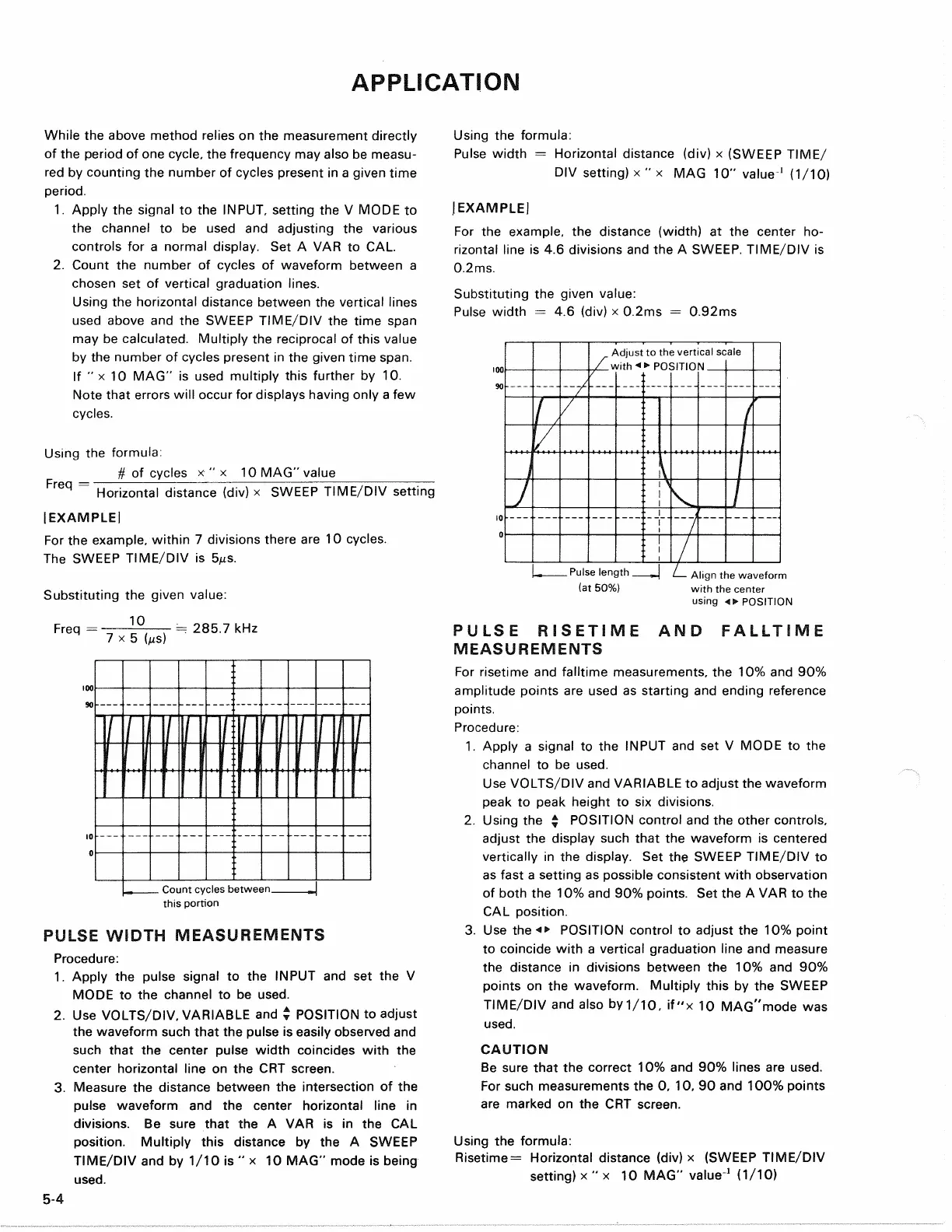
Pulse width = Horizontal distance (div) x (SWEEP TIME/
DIV setting) x " x MAG 10" value
1
(1/10)
JEXAMPLEI
For the example, the distance (width) at the center ho-
rizontal line is 4.6 divisions and the A SWEEP. TIME/DIV is
0.2ms.
Substituting the given value:
Pulse width = 4.6 (div) x 0.2ms = 0.92ms
Align the waveform
with the center
using «• POSITION
PULSE RISETIME AND FALLTIME
MEASUREMENTS
For risetime and falltime measurements, the 10% and 90%
amplitude points are used as starting and ending reference
points.
Procedure:
1.
Apply a signal to the INPUT and set V MODE to the
channel to be used.
Use VOLTS/DIV and VARIABLE to adjust the waveform
peak to peak height to six divisions.
2.
Using the ^ POSITION control and the other controls,
adjust the display such that the waveform is centered
vertically in the display. Set the SWEEP TIME/DIV to
as fast a setting as possible consistent with observation
of both the 10% and 90% points. Set the A VAR to the
CAL position.
3. Use the POSITION control to adjust the 10% point
to coincide with a vertical graduation line and measure
the distance in divisions between the 10% and 90%
points on the waveform. Multiply this by the SWEEP
TIME/DIV and also by 1/10, if"x 10 MAG"mode was
used.
CAUTION
Be sure that the correct 10% and 90% lines are used.
For such measurements the 0, 10, 90 and 100% points
are marked on the CRT screen.
Using the formula:
Risetime = Horizontal distance (div) x (SWEEP TIME/DIV
setting) x " x 10 MAG" value
1
(1/10)
Adjust to the vertical scale
with**
POSITION.
Pulse length
(at 50%)