85D01-051en202111 Manual TriBox3
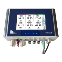
TriBox3 // Annex
6. Register tables
The registers in this document are numbered from 0 to 65535, which is the same numbering used in the Mod-
bus frames. If a software with a numbering starting from 1 is used, a 1 must be added to each register number
that can be found in this document in order to obtain the correct register number for that software.
Input and Holding use the same table, so there is no dierence between the results of the “Read Holding Reg-
ister” and the “Read Input Register” commands.
Attention: Due to internal adjustments to adapt the register usage to our sensors, some inconsistencies have
arisen, especially with regard to register arrangements of longer data types. It is possible that further adjust-
ments will follow.
6.1 Coils
There are numerous coils among the dierent devices which are used to trigger specic actions such as meas-
urements.
Register Supported devices Description
1 Sensors, TriBox Trigger a measurement. For sensors a measurement is triggered on
this sensor, for the TriBox a measurement for the entire measuring
system is triggered.
2 Sensors Resets the software status of the sensor.
3 TriBox Trigger a cleaning.
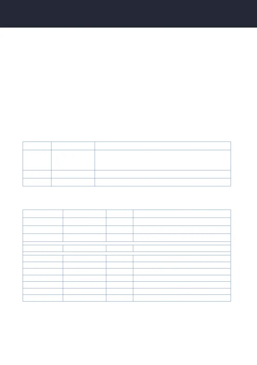
6.2 Registers of Modbus devices
Register range Datatype Read/Write Description
20 … 39 Char[40] R Name of the sensor, e.g. Opus_7123
80 Int16 R Number of measured values
81 DateTime R Time of last measurement
1000 R Measurement results (see below)
2000 R Spectrum (if the sensor has one)
2000 DateTime R Spectrum sample time
2006 Int16 R Integration time
2007 Int16 R Number of channels
2008 Int16 R Path length
2009 Float R CAL factor
2100 Floats R Spectral data
Measurement results
Depending on the sensor type, there are two dierent register mappings that are used here. If it is a TriOS
sensor that uses registers 1000 for its measurement results, the registers are mapped to the same registers
that are used in the sensor. Further information regarding the register numbers can be found in the respective
sensor manuals.