22
The Digital Controller can be connected to the Digital Mixer Processor unit in two ways,
these are: a) 10 metre data cable or b), wirelessly using AA sized batteries.
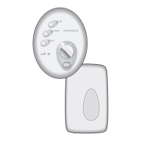
The Digital Controller has been designed to allow for the installation within a shower cubical
or above a bath. The controller must be located whereby the user can start and stop the
shower immediately.
Select the desired method of communication and then choose a suitable location for the
Digital Controller.
If using wired connectivity, the distance between the Processor unit and Controller
MUST BE within the range of the 10m data cable.
Data cable installation (Wired Connectivity Only)
If connecting the Digital Controller to the Digital Mixer Processor unit using the data cable,
the first operation is connect the data cable (ferrite end, see fig.13) to the Digital Mixer
Processor unit.
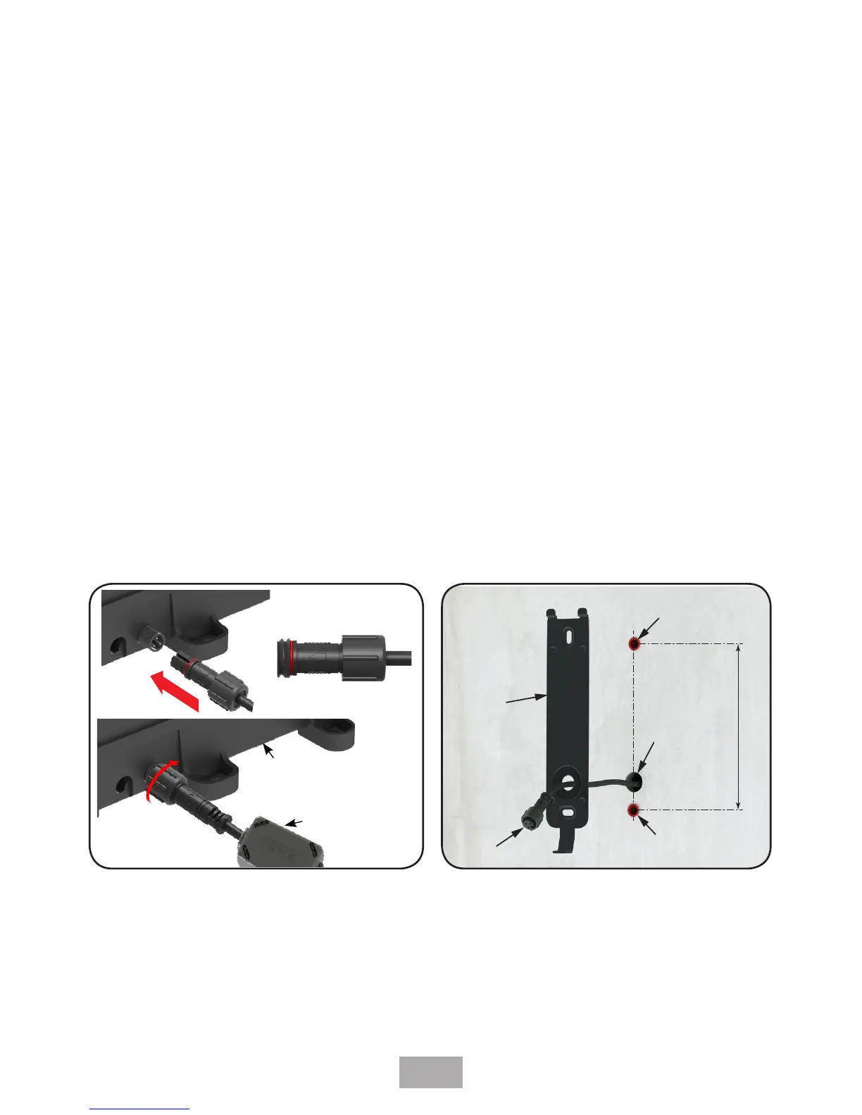
On the ends of both the Data Cable and Processor Data Cable Connector are screw
connectors, which provide a water tight seal. To ensure that the connectors are correctly
assembled and sealed, ALIGN the two arrows on both connectors so that they point
towards one another, and follow the 3 steps in (Fig 13).
A 15mm diameter hole needs to be made within the showering area to allow for the data
cable connection (Fig.14).
Make sure there is enough slack cable at the controller end in order for the Digital Controller
to be removed should the need arise for future maintenance. Approx 150mm protruding
length should be sufficient (Fig 15).
Under NO circumstances should the data cable be extended or shortened. The data
cable must be connected with the ferrite end attached to the processor unit, as
not only will it impair the performance of the shower but it will also invalidate the
guarantee.
1
2
3
Fig. 13
 Loading...