9EN
Connection
Observe the regulations!
The positive cable must have a 1 A fuse.
Lay the connector cable of the TIN bus and of the 12 V
operating voltage in loops without any tension. It must
be possible to pull the control panel approx. 20 cm out of the
installation opening without placing any tensile stress on the
plug connection. On no account pull on the connector cable
when it is connected to the control panel.
– Lay the connector cable (TIN bus) to the heater, air con-
ditioning system or Truma iNet Box and plug it in on the
Truma CP plus control panel.
– Plug in the 12 V connector cable and connect to an un-
switched 12V operating voltage (permanent positive). The
heater and the Truma CP plus control panel must be con-
nected on the same circuit.
TIN-Bus
CI-BUS
1
+
-
12 V
+ = red
-
= red / black
Figure 3 – Back view
1
Only in the case of variant Truma CPplus CI-BUS. An external
control panel (master) is connected at the factory.
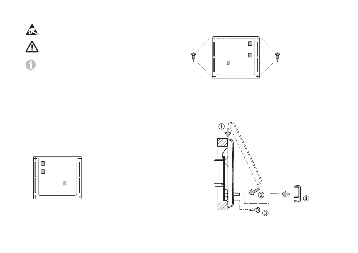
Assembly
– Fix the frame to the wall with 4 screws.
+
-
dia. max. 3.4 mm
Figure 4 – Front view
– Hook control panel upper section into frame using 2 latch-
ing lugs.
– Fix control panel upper section in position with a screw.
– Slide rotary push button onto axis.
Figure 5 – Installing the control panel upper section and ro-
tary push button
Subject to technical changes.