Part Two
Controller is not
controlling
(cont.)
Defective
variable
frequency drive
(VFD).
Perform test described in Control system is not controlling.
If Flow Control is functioning, verify wiring to VFD by
confirming control output voltage changes at VFD. If voltage
changes, a problem with VFD exists. See VFD manual for
further troubleshooting.
Damper/Valve is
full open or full
closed, won’t
move.
Control wires are loose. Check wires and verify control
output is working (see No control output signal). If control
output test passes, verify damper/valve is moving in correct
direction (see Damper/Valve moving opposite direction). If
damper/valve is moving correctly and set point cannot be
reached, DIM will fully move damper/valve to get as close to
set point as possible. Exhaust; fan, static pressure, etc.
needs to be adjusted.
Sensor does not
calibrate.
Incorrect
pressure sensor
address.
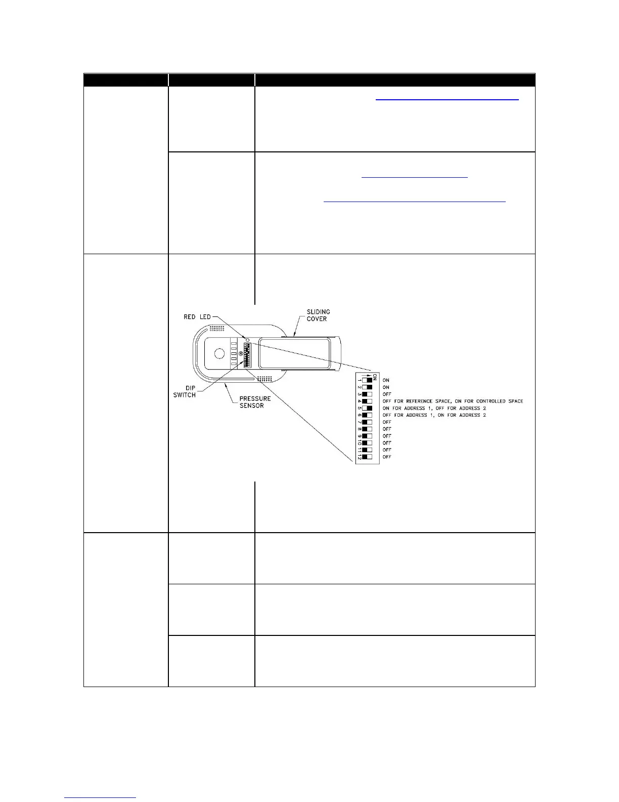
Rm1 pressure sensor must have address of 1. Anteroom
sensor must have address of 2. Check pressure sensor DIP
switches 1 & 2 and verify address is correct (7 to 12 must
be OFF).
Figure 19: Pressure sensor DIP switch
Sensor
communications
not working.
Check SENSOR STAT item in diagnostics menu. If
NORMAL is displayed, sensor is okay. If COMM ERROR is
displayed, check wiring, pressure sensor address, and that
DIP switch 1 & 2 are ON (Figure 19).
Pressure sensor
red LED is
blinking
(Figure 19).
Problem with
sensor (slow
uniform blink).
Check SENSOR STAT and confirm NORMAL is displayed.
If ERROR is displayed, correct error.
Communication
(fast burst of
non-uniform
blinking).
Unit is communicating with DIM. This is normal.
Red LED is
constantly on or
blinks every 5
seconds.
This is normal when no problems exist or when no
communication is occurring.
 Loading...