TSN Box Development – TSN Box 3.0 Getting Started Guide
Pin Number 1 2 3 4 5 6 7 8
Wire Colour White /
Orange
Orang
e
White /
Green
Blue White /
Blue
Gree
n
White /
Brown
Brown
Description TX + TX - RX + NC NC RX - NC NC
2.4.11
CAN Module
The CAN Module consists of aCAN bus interface over a DE-9 connector. A 'straight' DE-9 cable is supplied with the
unit. Note that the 12V supplied on pin 9 of the connector is a build option and does not come standard.
The mating connector is a standard DE-9maleconnector.
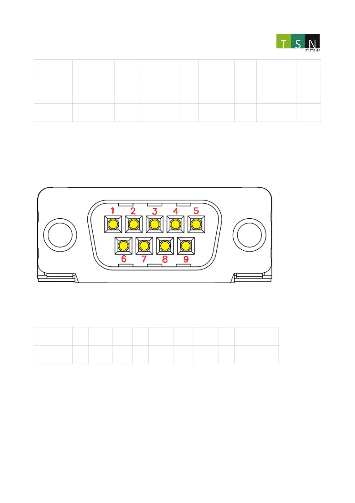
2.4.11.1 Pinout
Pin Number 1 2 2 4 5 6 7 8 9
Description NC CAN-L GND NC Shield GND CAN-H NC 12V (Optional)
2.4.11.2 Termination Switches
When both switches are in theONposition, a 120Ωtermination resistance is addedbetween the CAN-H and CAN-L
bus signals. Both switches should be in the same position at all times for correct operation.