TSN Box Development – TSN Box 3.0 Getting Started Guide
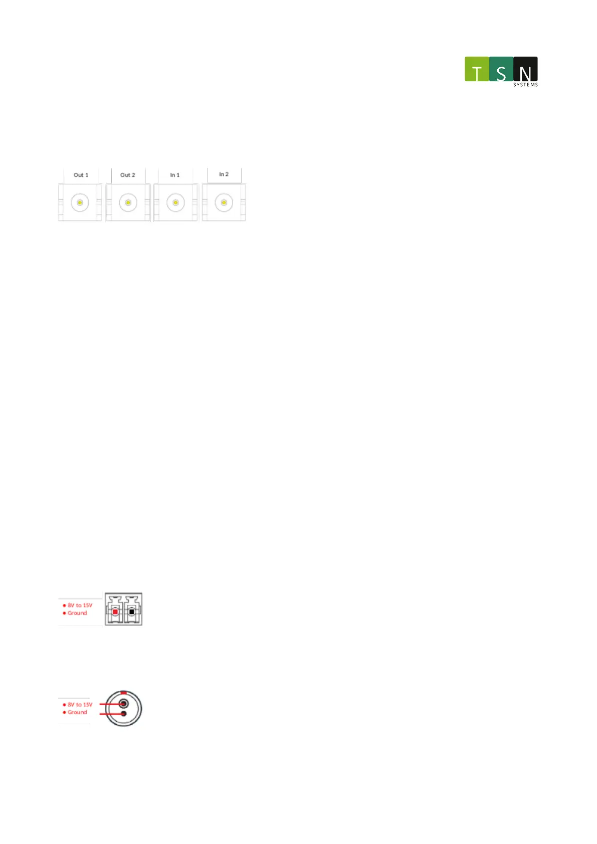
2.4.13 PPS IO
The PPS IO consists of 2x output channels and 2 input channels over 4x SMA connectors. These signals function
identically to the PPS channels on the SYNC board, including the 50Ω impedance.
Each shell is connected to signal ground.
The electrical specifications are the same as theSYNC ModulePPSmodeabove.
2.4.14 Reset
This button is placed behind a pin hole, and can be reached with a pin at least 5mm in length. Using this button
causes a cold restart by triggering the reset pins on the FPGA and the host CPU.
2.4.15 Recovery Button
This button is placed behind a pin hole, and can be reached with a pin at least 5mm in length. This button is to be
used as emergency software recovery mode / factory restore.
2.4.16 Power
There are two power jacks on the unit, both directly electrically connected in parallel. The circular connector is a
specialized plug that mates with the accompanying power supply. The green Terminal Block Header can be used to
daisy chain multiple units. Acompatible connector is supplied.
Theinput voltage range is 8V minimum to 15V maximum.
The typical current load of the unitis 1.5A with a maximum load of 2.3A.
Ensure that the power supply can handle this maximum load when daisy chaining multiple units.
2.4.16.1 Terminal Block Header (Green)
The mating connector of the terminal blockpower connector is the Phoenix Contact1840366.
Circular Connector (Silver)