Page 57 of 102
TVL 351
ISSUE 15
E2 Car Module (Rev 4)
Precautions
The module must be mounted in suitable protective box or car top terminal box. Observe
normal precautions for handling electronic devices, avoid static electricity, dampness and
extreme temperatures. Please read this instruction sheet full y before use.
Specification
Supply Voltage 24V d.c.
Board Operating Current 300mA
Max Input Voltage (FI1-8) 24V d.c.
Max Output Current Call Outputs 300mA @ 24V d.c.
(per output, LED type indicators only)
Max Output Current Feature Outputs 2A @ 24V d.c.
(FO1-11, per output)
Max Output Current BZ Output 1A @ 24V d.c.
Output Short Circuit Protection Yes
Serial Connections USB (device), RS232, RS485
Dimensions (in DIN carrier) 210 x 90 x 60mm
Standards EN81-20/50 (EN81-1/2)
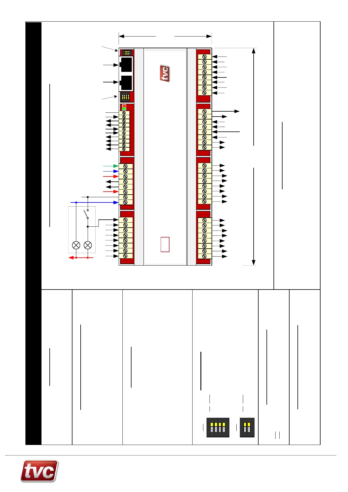
Typical Wiring and Dimensions of Car Module
Car push with acceptance
indi cator and dual-
illumination
+
-
DIP Settings
DIP Name
4 Test Mode
3 Side
2 Spare
1 Spare
DIP 3 to set side
OFF = Front
ON = Rear
DIP 4 for test mode (normally off)
Loop and Fault LED’s
The Green LED (D1) will flash every 2 seconds to signify power to node and
that the node is running.
The Red LED (D2) will light continuously for 4 seconds when the node is first
powered up. After this point the red LED signifies various fault codes. The LED
will do a quick flash every 4 seconds if the node has a fault.
ON
1 2 3 4
SW2
DIP Name
2 CAN Term
1 CAN Term
DIPs 1 and 2 on for CAN termination
These should only be set on the last
node in the network.
SW3
ON
1 2
Jumper / Reset Settings
SW4 Place Jumper in the upper position for normal operation, lower for programming.
SW5 Reset Switch press to reset board.
1 flash every 4 secs = Node not communicating with Ethos or EM U.
2 flashes every 4secs = Node is experiencing data bus faults.
3 flashes every 4 secs = N ode has stopped transmitting due to bus faults.
4 flashes every 4 secs = N ode has stopped transmitting or receiving from the
data bus
90mm
210mm
0V Car cal l return
24V d.c. CPF
Car call feed
4 x inputs
24V d.c. max
1 - 4 return
0V d.c.
USB Device Connection J2
The Car Module board has a USB micro device connector for programming and also to
output monitoring data from the built in 3 axis accelerometer, this is used for TVC factory
setup only.
Combined Car / Door Node Module
Front or Rear
ON
1
2
ON
1 2 3 4
5 - 12 return
0V d.c.
8 x inputs
24V d.c. max
9 volt free relay outputs
(2A @ 24V d.c. / 110V a.c max)
Output for
buzzer
Module
power
Outputs
10-11
(2A @ 24V
d.c. max)
RS232 to
CARDIP
CAN Network
from Ethos and
to other
modules
Network
termination
Front / rear
+ test dips
Car push return
Ethos 2 Car Module (Rev 4)
The Car Module is designed to be mounted on the lift car. It is used to supply Ethos 2 with
door and other car COP signals. The unit has a built in 3-axis accelerometer for ride profile
monitoring, so must be mounted securely to avoid false triggering of the accelerometer.
I/O includes:- 11 volt free relay outputs, 12 x 24V d.c. feature inputs and 8 call I/Os. These
can be configured via the Ethos 2 MMI.
An RS232/485 connection is supplied to drive car indicators or speech units.
Please consult main drawings for contract specific wiring and setup.
24V
24V
0V
Earth
Output 1
N/C contact
C1
C2
C3
C4
C5
C6
C7
C8
FO1B
FO2A
FO2B
FO3A
FO3B
FO4A
FO4B
0VR
CPR
CPF
BUZA
BUZB
ETb
0V
24V
FO5A
FO5B
FO6A
FO6B
FO7A
FO7B
FO8A
FO8B
FO9A
FO9B
FI1
FI2
FI3
FI4
FIC1
FIC2
FI5
FI6
FI7
FI8
FI9
FI10
FI11
FI12
CANb
CANa
FO10A
FO10B
FO11A
FO11B
C0V
RX
TX
RTS
CTS
ETa
Car Module
V4
FO1A