Page 59 of 102
TVL 351
ISSUE 15
E2 I/O Feature Modules
Precautions
The modules must be mounted in suitable protective box or car top terminal box. Observe
normal precautions for handling electronic devices, avoid static electricity, dampness and
extreme temperatures. Please read this instruction sheet fully before use.
8 Input Feature Modules
Loop and Fault LED’s
The Green LED (D3) will flash every 2 seconds to signify power to node and that the
node is running.
The Red LED (D5) will light continuously for 4 seconds when the node is first
powered up. After this point the red LED signifies various fault codes. The LED will
do a quick flash every 4 seconds if the node has a fault.
1 flash every 4 secs = Node not communicating with Ethos 2.
2 flashes every 4secs = Node is experiencing data bus faults.
3 flashes every 4 secs = Node has stopped transmitting due to bus faults.
4 flashes every 4 secs = Node has stopped transmitting or receiving from the data
bus
Ethos 2 - I/O Feature Modules
The I/O Feature Modules are designed to be mounted on the panel or on the lift car.
They are used to supply Ethos 2 with signals to and from the lift system. The
modules are available in 2 versions of 8 way input and an 8 way output.
Consult panel drawings to determine which inputs and outputs have been assigned
to which module fitted.
I/O includes:-
8 Output modules, these are designed to switch up to 110V a.c.
8 Input 110V (.1) modules, these are designed to take 110V a.c. / d.c. inputs.
8 Input 24V (.2) modules, these are designed to take 24V a.c. / d.c. inputs.
The feature cards can be configured via the Ethos 2 MMI.
Please consult main drawings for contract specific wiring and setup.
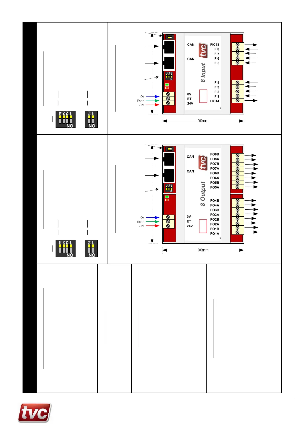
Module
power
CAN Network
from Ethos and
to other
modules
Network
termination
Node number
+ test dips
ON
1 2
90mm
Specification
Supply Voltage 24V d.c.
8 Way Input Board
Board Operating Current 50mA
Max Input Voltage (FI1-8) 110V 110V a.c. / d.c. (.1 version)
Max Input Voltage (FI1-8) 24V 24V a.c. / d.c. (.2 version)
Dimensions (in DIN carrier) 90 x 90 x 60mm
8 Way Output Board
Board Operating Current 150mA
Max Output Current Feature Outputs 2A @ 110V a.c
Max Output Current Feature Outputs 500mA @ 24V d.c.
(FO1-8, per output)
Dimensions (in DIN carrier) 105 x 90 x 60mm
Standards EN81-20/50 (EN81-1/2)
5 - 8 return
0V
4 x inputs
110V / 24V max
(build dependant)
1 - 4 return
0V
4 x inputs
110V / 24V max
((build dependant)
Module
power
CAN Network
from Ethos and
to other
modules
Network
termination
Node number
+ test dips
105mm
ON
1 2
8 Output Feature Module
8 volt free relay outputs
(500mA @ 24V d.c. / 2A @ 110V a.c max)
8 Input DIP Settings8 Output DIP Settings
DIP Name
4 Test Mode
3 Spare
2 B2 Node Num
1 B1 Node Num
DIP 4 for test mode (normally off)
DIPs 1 to 2 Set node number 0 to 3,
Maximum of 4 nodes = 32 outputs.
SW2
DIP Name
2 CAN Term
1 CAN Term
DIPs 1 and 2 on for CAN termination
These should only be set on the last
node in the network.
SW3
DIP Name
4 Test Mode
3 Spare
2 B2 Node Num
1 B1 Node Num
DIP 4 for test mode (normally off)
DIPs 1 to 2 Set node number 0 to 3,
Maximum of 4 nodes = 32 inputs.
SW2
DIP Name
2 CAN Term
1 CAN Term
DIPs 1 and 2 on for CAN termination
These should only be set on the last
node in the network.
SW3
J5
SW2
J6 J7
SW2
J5
J7J6