This document is an instruction manual for the ULVAC PMB-040C and PMB-060C mechanical booster pumps, providing essential information for safe and effective operation and maintenance.
Function Description
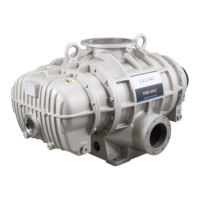
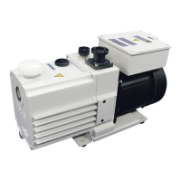
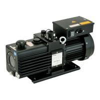
The mechanical booster pump is designed to enhance exhaust speed, particularly in the pressure range of 8.0×10² to 6.7×10⁻¹ Pa, where the backing pump's exhaust speed tends to decrease. It operates in conjunction with a backing pump (such as a dry pump or oil rotary pump). The pump features two cocoon-shaped rotors enclosed within a casing, designed to rotate in opposite directions without contact, maintaining a small clearance between them via a timing gear. This non-contact rotation prevents wear on the rotors and casing. Since no lubricating oil is used in the rotor chamber, the pump offers stable pumping performance even when handling water vapor and solvent vapor.
The pump cannot be started at atmospheric pressure and must always be used in combination with a backing pump. Rough-pumping of the vacuum chamber and piping is required until the pressure lowers to the booster pump's operating range before it can be started. Two rough-pumping methods are described: one where rough-pumping occurs through the mechanical booster pump (suitable for small vacuum chambers or when a longer rough-pumping time is acceptable), and another where a dedicated rough-pumping path is provided (for larger vacuum chambers to shorten rough-pumping time).
Important Technical Specifications
The PMB-040C and PMB-060C models have distinct specifications:
Pumping Speed:
- PMB-040C: 3800 m³/h
- PMB-060C: 6200 m³/h
Maximum Intake Pressure: 8.0 × 10² Pa (continuous operation from maximum suction pressure to 400 Pa should be within 20 minutes).
Ultimate Pressure: 6.7 × 10⁻¹ Pa (measured with a Pirani gauge, approximately 6.7 × 10⁻² Pa for MacLeod vacuum gauge).
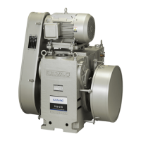
Backing Pump:
- PMB-040C: PKS-070 × 1
- PMB-060C: PKS-070 × 2
Motor: Totally-enclosed Fan-cooled Footed Induction Motor (IE3 energy efficiency class).
- PMB-040C: 15 kW (4 poles)
- PMB-060C: 18.5 kW (4 poles)
- Available in 200V class (50Hz/60Hz) and 400V class (50Hz/60Hz).
Oil: ULVAC R-72 (mineral oil).
Oil Requirement: 8 L.
Weight (Without motor, dry):
- PMB-040C: 970 kg
- PMB-060C: 1100 kg
Inlet/Outlet Flanges:
- PMB-040C: Inlet VG250 equivalency, Outlet VF150 equivalency.
- PMB-060C: Inlet VG300 equivalency, Outlet VF200 equivalency.
- Flange for vacuum devices (JIS B 2290:1998).
Packing: Fluorocarbon rubber.
Cooling Method: Water cooling.
- Cooling water volume: 10 L/min or more.
- Primary side pressure: 0.1-0.3 MPa.
- Inlet/outlet differential pressure: 0.05 MPa.
- Cooling water temperature: 5-30 °C (use in non-dewy environment if water temperature is low).
Ambient Conditions for Storage, Install, and Operation:
- Storage temperature: -10°C to 60°C, less than 95%RH (no freeze/condensation).
- Operation temperature: 5°C to 40°C, less than 80%RH (no condensation).
- Height: Lower than 1,000 meters altitude.
- External vibration: Less than 114dB (0.5G) acceleration.
- No corrosion, explosive gas, freeze, dew formation, or dust.
- Indoor use only.
- No direct sun beam or heat sources nearby.
Usage Features
Installation:
- The pump must be installed horizontally and securely fixed with anchor bolts to prevent free-running and damage to peripheral devices.
- Minimum space for maintenance should be considered during layout.
- Inlet and outlet piping should be connected using JIS vacuum flanges and bellows to absorb pump vibration.
- A vacuum valve, vacuum gauge, and leak valve should be placed between the vacuum chamber and the pump.
- Exhaust ports are provided at both the bottom and side; one must be connected to the backing pump, and the other sealed with a blind flange and O-ring.
- Cooling water piping must be connected in parallel if multiple pumps are used. A flowmeter for cooling water is recommended, with an interlock to stop the pump if flow is insufficient.
- Water quality for cooling is important; industrial water with low impurities is recommended to prevent scale, corrosion, or metal elution.
- During operation stop in winter, cooling water should be drained to prevent freeze-up and damage.
Electrical Connection:
- A three-phase current motor is used, requiring an overload protective device connected through the motor to the power supply. A leakage breaker is also recommended.
- IE3 motors have higher efficiency but also higher striking current, so careful selection of MCCB, ELCB, and THR (time-lagged type recommended for thermal protection) is necessary to avoid instantaneous action.
- Wiring must comply with safety laws and regulations. Proper grounding is essential to prevent electrical shock.
- The electric wire size should be chosen to keep voltage drop within 2% of the motor rated voltage.
- Direct-in start connection is recommended; Star delta connection may cause starting issues.
- The motor's rotation direction must match the arrow on the belt cover.
Operation:
- Never run the pump with the exhaust outlet blocked or any device obstructing gas passage, as this can cause pressure buildup, casing/oil level gauge breakage, or motor overload. The ensured pressure value is 0.03MPa G (0.3kg/cm²G).
- Do not operate in hazardous areas with explosive gases.
- During operation, the pump and motor can reach high temperatures; avoid touching them until sufficiently cooled.
- Ensure cooling water flows at the specified volume and temperature during operation. Insufficient cooling can damage bearings, gears, and rod sealing.
- Lubrication oil level must be maintained within the specified range.
- If the pump sucks water or substances like dust/powder, it can impair ultimate pressure and cause operational issues due to the very small clearance between rotating parts.
- Welding scale or rust in pipes must be completely cleared before connection.
- A metal mesh on the suction inlet prevents foreign substances from entering the pump.
- When using an automatic vacuum breaker, ensure it is connected to interlock with the motor.
- Before starting, check piping, cable connections, belt tension, lubrication oil level, and cooling water flow.
- Perform lubrication deaeration and circulation by running the backing pump for at least three minutes to exhaust air components from the lubrication oil.
- Check the motor's rotation direction during a brief 3-second run. If reversed, check motor wire connections.
- After stopping operation, close the main valve, allow the rotor to stop due to inertia, open the suction leak valve to equalize pressure, and wait for the pump to cool before stopping cooling water flow.
Maintenance Features
Regular Checks:
- Conduct daily visual checks and utility checks.
- At least once every three days (more frequently for high-load operation), check:
- Oil amount and discoloration.
- Oil leakage from the pump and mechanical seal.
- Cooling water flow and leakage.
- Abnormal noise or vibration.
- Motor current value.
- Before any check or repair, turn off the power supply and ensure the pump has cooled down.
Lubrication:
- Lubrication oil (ULVOIL R-72) must be supplied separately to the gear side and pulley side lubrication chambers, filling up to the upper limit of the oil level gauges.
- The oil level should be checked during operation, remaining within ±5mm of the red round mark on the oil gauge.
- Use only ULVAC-designated vacuum pump oil.
- Stop the pump and return the mechanical booster to atmospheric pressure before lubricating.
- If the pump has been stopped for more than 3 months or relocated, lubricate the mechanical seal by discharging existing oil and adding about 500ml of new oil.
- Overfilling oil at room temperature can cause oil to flow into the casing.
- Pump oil can deteriorate quickly depending on use conditions; the first replacement is recommended within ten days, with subsequent cycles determined by contamination levels.
V-belt Check and Replacement:
- Check belt tension every six months. Re-tension if necessary. Replace if abnormal.
- Initial tension adjustment is required 24 hours and one week after initial start-up due to extension and pulley groove settling.
- Measure belt tension using a tension meter, applying load to achieve a specified deflection.
- Regulate belt tension once a month after starting operation.
Oil Leakage:
- Slight oil leakage from mechanical seals is normal during the running-in period (approx. one month after startup).
- If leakage exceeds 0.3 ml/hour after a certain period, mechanical seals may need replacement.
Casing Inspection:
- Every three months, remove air intake piping and check inside the casing for deposits on rotors and casing surfaces, especially when exhausting organic gases that may condense.
Overhaul:
- Recommended annually, or earlier if significant contamination or performance deterioration occurs.
- Overhaul is necessary to maintain performance and safety.
- Contact ULVAC Service Center for overhaul.
- A "Certificate of Contamination" must be filled out and submitted for repair/inspection requests, especially if hazardous substances were used. ULVAC may refuse service if hazardous substance details are not disclosed or detoxification is difficult.
Disposal:
- Dispose of the vacuum pump in compliance with local laws and regulations.
- If toxic gases were exhausted, a dedicated disposal agency must be used, as the pump oil and unit become hazardous.
- Refer to the Chemical Material Safety Data Sheet (SDS) for disposal precautions for pump oil.