YK10-0015-DI-002-03
5
2. Pump Outline
2.1 Total configuration
The Mechanical booster pump is used combined with the backing pump to enhance the exhaust
speed around the pressure range 8.0×10
2
~ 6.7×10
-1
Pa where the backing pump exhaust speed
is likely to lower.
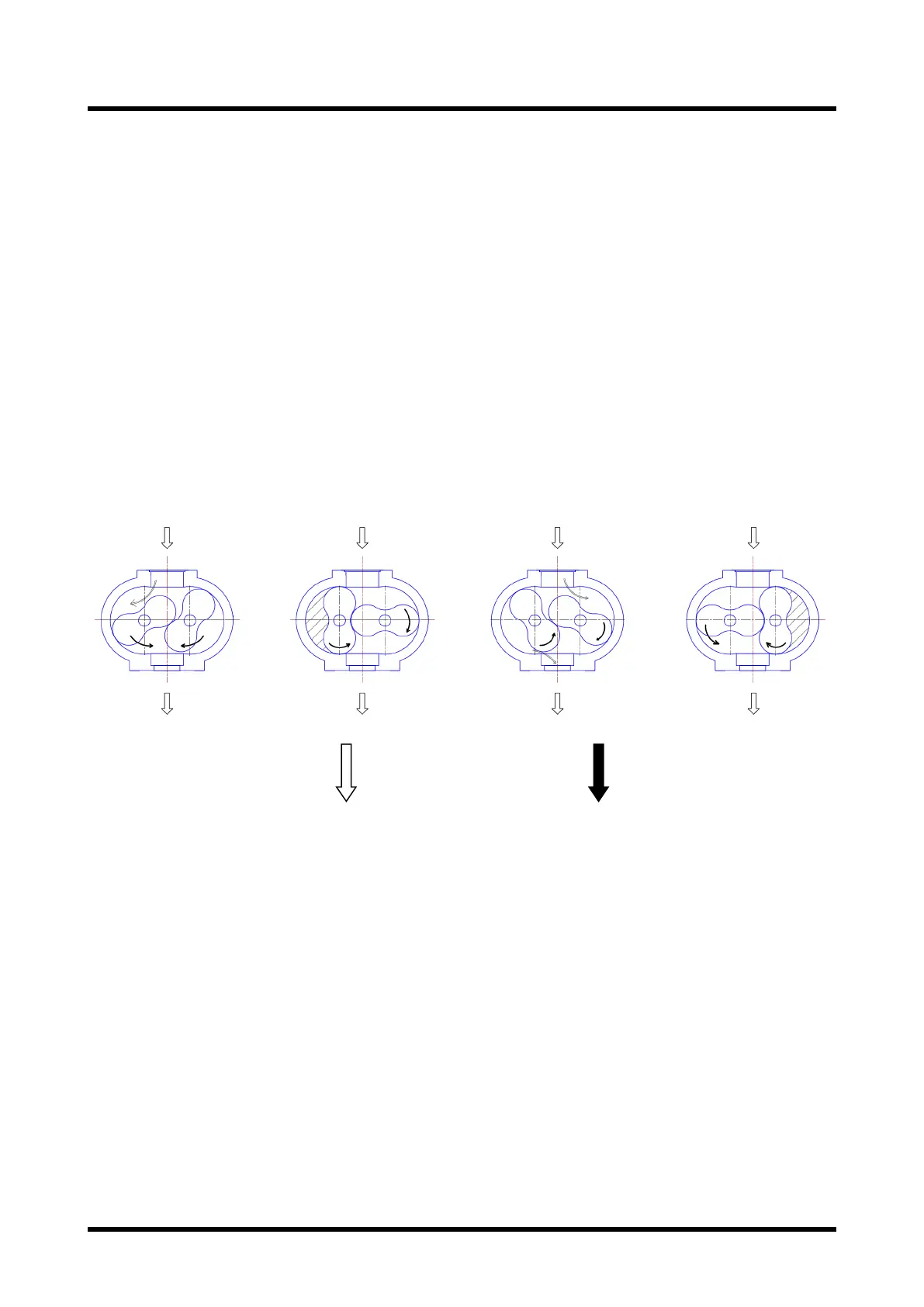
The mechanical booster pump includes two rotors having a cocoon-shaped cross section and a
casing that encloses them. These rotors are designed to rotate in the opposite directions without
contacting each other while maintaining a very small clearance between them by a timing gear.
The rotors and the casing are constructed in such a manner that the rotors can rotate while
maintaining a small clearance between the rotor and the casing.
Fig. 2 Pumping mechanism of mechanical booster pump
With this type of pump, there is no fear of the rotors and casing being worn out because they do not
contact each other during rotation. Since no lubricating oil is used in the rotor chamber, stable
pumping performance can be obtained even for water vapor and solvent vapor.
2 1 3 4
: The arrow shows the
gas flow.
: The arrow shows the
rotor rotation.