UTD2000 Series User Manual
18
Figure 2-4 Waveform Display When Setting Bandwidth throttling in OFF Position
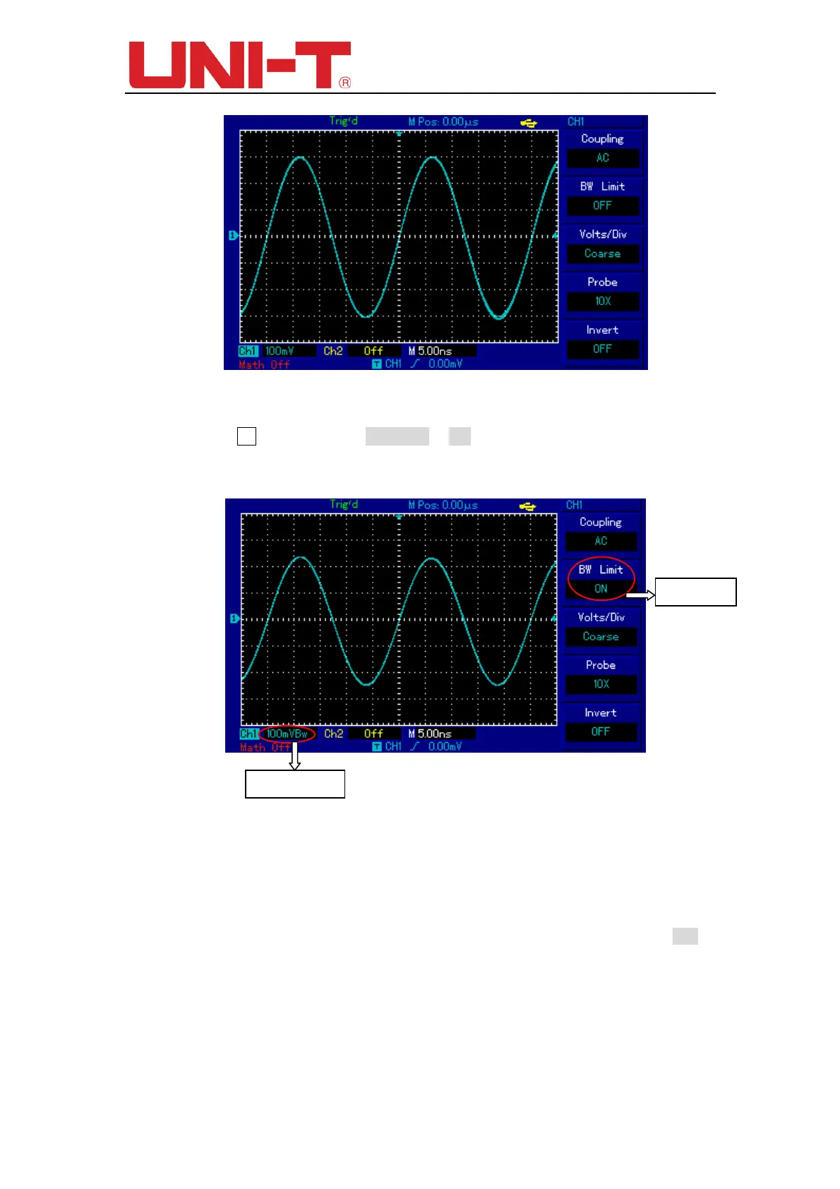
If you press F2 again to set the BW Limit as ON, the noises or high-frequency
component over 20MHz in measured signal shall be attenuated, as waveform display
shown in figure below.
Figure 2-5 Waveform Display When Setting Bandwidth throttling as ON
2.3 Setting probe Rate
In order to cooperate with attenuation coefficient setting of probe, it is required to set
the probe attenuation coefficient in channel function menu. If the probe attenuation
coefficient is 10:1, the probe coefficient in channel function menu shall be set to be 10×
and vice-versa.
BW Limit ON
BW Limit Mark
 Loading...

