UTD2000 Series User Manual
13
1.3 Probe Compensation
When connecting the probe with any input channel for the first time, it is required to
make adjustment for this item, matching the probe with input channel. Probe without being
compensated and corrected will lead to measurement error or mistake. In case of
adjustment of probe compensation, follow the following steps:
(1) Set the probe menu attenuation coefficient as 10×, place the switch on the probe
at 10× and connect DSO probe with CH1. Connect the probe end and signal output
connector to the probe compensator, the ground clamp and ground lead connector of
probe compensator, turn on CH1 and press AUTO.
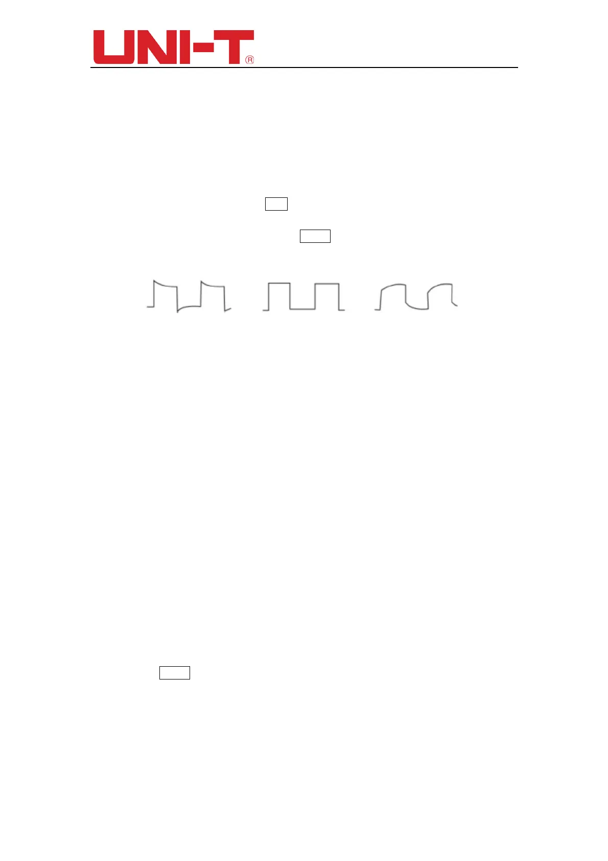
(2) Observe displayed waveform
Figure 1-5 Probe Compensation and Correction
(3) If screen displays “under-compensation” or “over-compensation” for waveform as
shown in above figures, use screwdriver with nonmetal handle to adjust the variable
capacitance on the probe until screen displays “correct compensation” for waveform as
shown in the below figure.
Warning: in order to avoid electric shock when measuring high voltage with
probe, please ensure that the insulation lead of the probe is in good condition and
do not contact the metal part of the probe when connecting high pressure power
supply.
1.4 Automatic Settings of Waveform Display
UTD2000 series DSO has automatic setting function. According to input signals,
automatically adjust the vertical deflection factor, scanning time base and trigger mode
until the most appropriate waveform is displayed. Apply automatic setting, the frequency
of the measured signal is required to be ≥ 50Hz and the duty ratio is > 1%.
Apply automatic setting:
(1) Connect measured signal to signal input channel.
(2) Press AUTO key. DSO will automatically set its vertical deflection factor, scanning
time base and trigger mode. If further careful observation is required, adjustment can be
conducted again after automatic settings until the waveform display reaches required
optimum effect.
1.5 Introduction to The Vertical System
As shown in the figure below, there are a series of keys and knobs in the vertical
Over-compensation
Correct compensation
Under-compensation
 Loading...

