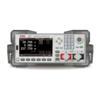
Programable DC Electronic Load User Manual
12
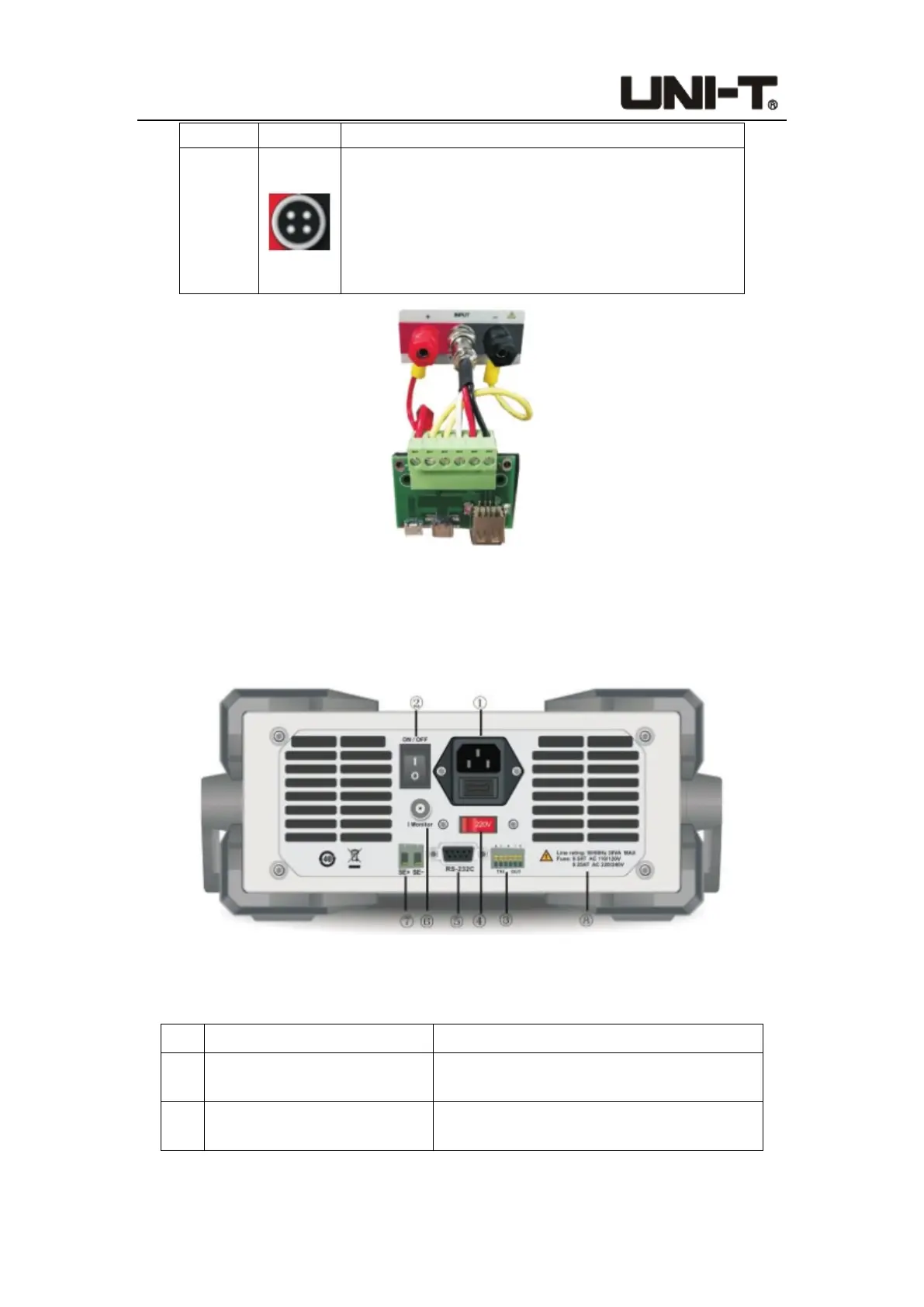
1-2-3.
7-Middle
It is the male end of the quick-charging connector.
These 4 pins are used to connect the 4 terminal holes
of the female end of the quick-charging test board
assembly, as shown in Figure 1-2-3. Note: This jack
socket has a fool-proof design. You need to carefully
align the direction before matching.
Figure 1-2-3 Connection of Terminal and Quick Charge Test Board (UTL8511C)
1.3 Rear Panel
Figure 1-3-1 Rear Panel
Table 1-3-1 Introduction of Rear Panel
No. Items Description
①
AC220/110V socket AC power input socket (with fuse)
②
ON/OFF power button
 Loading...