Programable DC Electronic Load User Manual
38
edge of the voltage, it starts timing and triggers at the set trigger voltage. The load records
the voltage at the peak point, and calculates the time from the peak point to the trigger
point. After the measurement, the load will display the tested Vmax (peak voltage) and
Tgap (protection time). The measurement accuracy of the protection time is 1mS.
Operation steps:
1. In initial interface, select [Mode], [More], [More], and then press [OVP] to enter the
setting interface.
2. Move the cursor to the needed setting position by pulse knob, and press the Enter
button to change the parameter (the parameter changes from yellow to white)
by keyboard or pulse knob. Press the Enter button again to confirm. At this time,
the set value changes from white to yellow.
3. Other parameters can be modified in a similar way.
4. Press the ON button, the electronic load starts to load, and the indicator light below
the button lights up. If users need to stop the load, press the ON button again, and the
running indicator light goes out.
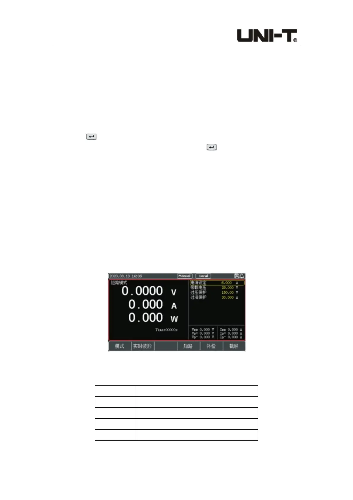
4.2.9 Short-Circuit Mode
The electronic load can simulate a short-circuited circuit at the input terminal to test
whether the protection function of the measured object can operate normally when the
output terminal of is short-circuited.
Figure 4-2-9-1 Interface of Short-Circuit Mode
Parameter setting in short-circuit mode:
Parameter Description
Current Load current value in normal status
V on Set the starting voltage
V Limit Constant value of overvoltage protection
C Limit Constant value of overcurrent protection
 Loading...