Programable DC Electronic Load User Manual
32
button to change the parameter (the parameter changes from yellow to white)
by keyboard or pulse knob. Press the Enter button again to confirm. At this time,
the set value changes from white to yellow.
3. Other parameters can be modified in a similar way.
4. Press the ON button, the electronic load starts to load, and the indicator light below
the button lights up. If users need to stop the load, press the ON button again, and the
running indicator light goes out.
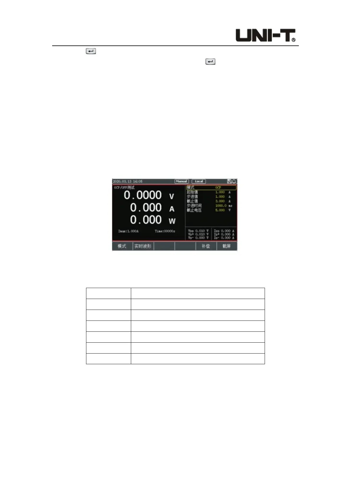
4.2.4 OCP/OPP Mode
This mode is used to detect the protection function of the tested power supply under
overload conditions. UTL8500X series electronic load has two test modes: OCP/OPP.
Figure 4-2-4-1 Interface of OCP/OPP Mode
Parameter setting in OCP/OPP mode:
Parameter Description
Mode OCP/OPP
Start value Set the initial value of the test mode
Step value Set the step value in every step time
End value Set the maximum end value of the test mode
Step time Set the time interval of every step
End voltage Set the minimum end voltage
In OCP/OPP mode, users continuously increase the load value by setting the start value,
step value and step time until the end value is reached or the protection point of the
measured object is detected, and the test stops.
 Loading...