Programable DC Electronic Load User Manual
33
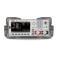
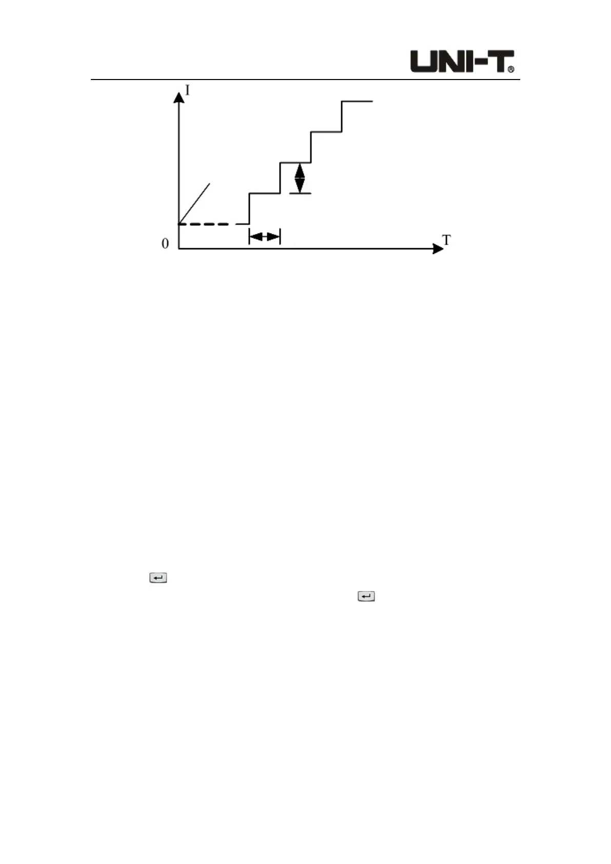
Figure 4-2-4-2 OCP/OPP Mode
Description of OCP/OPP mode:
Since OCP/OPP mode will continuously increase the output power of the tested object,
please input reasonable load parameters during the test to avoid damage to the tested
object. After the test is over, the electronic load will display the time of this test and the
current/power value of the peak point.
Test results of OCP/OPP mode:
When the protection value of the test result is less than the end value, it is Pass; when it
exceeds the end value, it is Fail. On the software framework, there are only two pop-ups
for passing and failing the test, and no judgment pop-ups. Therefore, when the selected
mode does not have a judgment item, that is, the pass pop-up pops up, but it is not used
as judgment, but only as a test end prompt.
Operation steps:
1. In initial interface, select [Mode], [More], and then press [OCP/OPP] to enter the
setting interface.
2. Move the cursor to the needed setting position by pulse knob, and press the Enter
button to change the parameter (the parameter changes from yellow to white)
by keyboard or pulse knob. Press the Enter button again to confirm. At this time,
the set value changes from white to yellow.
3. Other parameters can be modified in a similar way.
4. Press the ON button, the electronic load starts to load, and the indicator light below
the button lights up. If users need to stop the load, press the ON button again, and the
running indicator light goes out.
4.2.5 CR-LED Mode
The CR-LED mode is a test mode for the LED power supply. By simulating the conduction
voltage and working current of the light-emitting diode, the working principle of the LED is
Start current
Step current
Step time
 Loading...