Programable DC Electronic Load User Manual
71
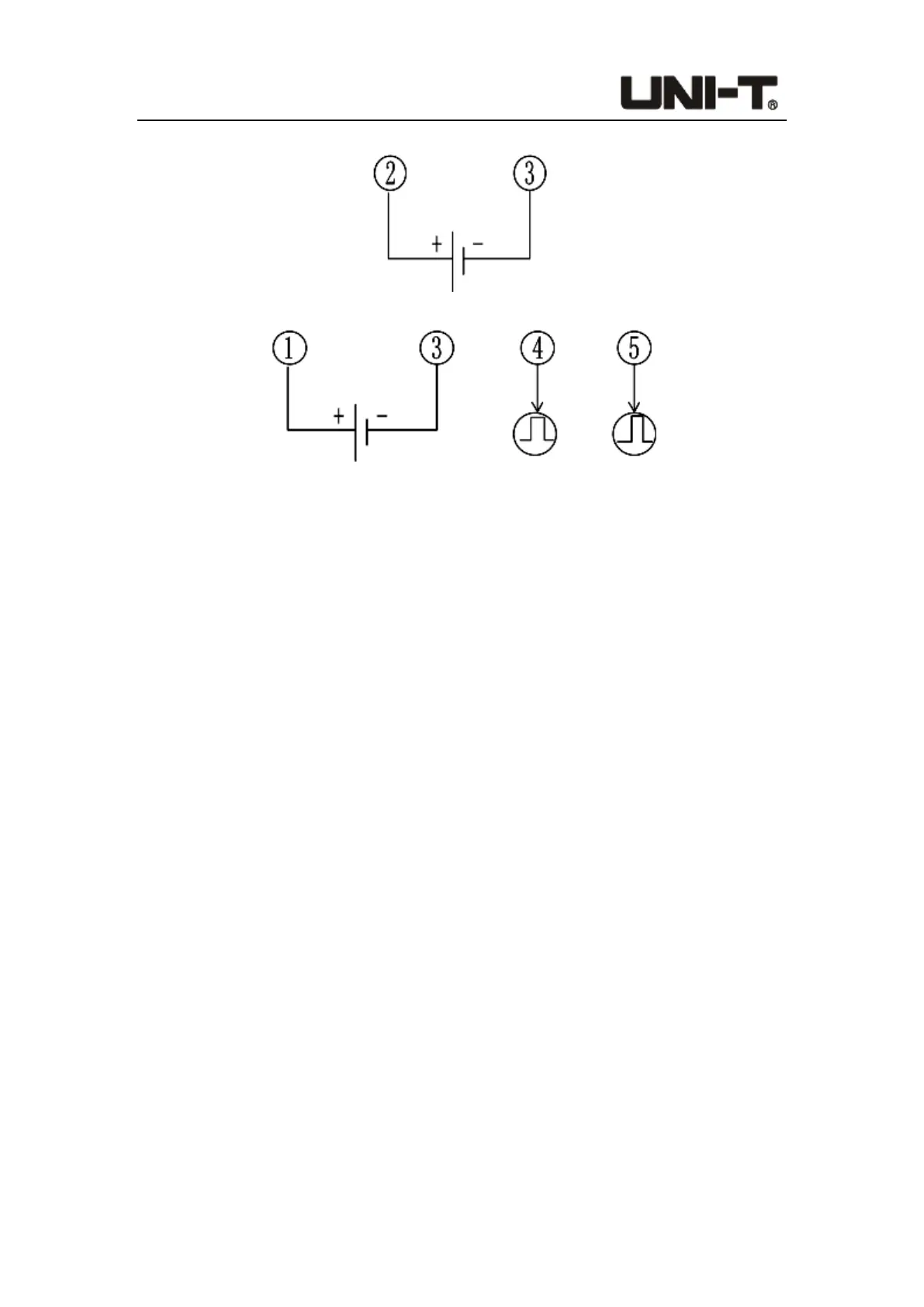
2. Wiring method for active trigger input (external power signal)
3. Wiring method for test result output (need external power supply)
Note:
1) The voltage range of all external power supplies shall not exceed DC5V~DC24V.
2) The maximum withstand current of the test result output terminals (④ and ⑤) is
20mA.
3) Due to the internal opticalcoupler, when the terminals ④ and ⑤ output high level,
the high level voltage will be about 1V lower than the external power supply voltage.
4) When the test result is correct, the terminal ⑤ outputs a high level of about 500ms.
When the test result is wrong or fails, the terminal ④ outputs a high level of about
1500ms. The terminals ④ and ⑤ are both low level when there is no output.
5) The trigger input adopts positive transition edge input. Once the passive switch is
closed (or the trigger voltage signal is loaded), it indicates that the trigger signal input
has been completed. When triggering again, the operation needs to be redone.
6) When the terminal ① is connected to the external power source positive, either
passive trigger or active trigger can be used normally. It is recommended that passive
trigger input be used at this time.
8. Technical Specifications
● Main Technical Parameters
● Notes on Calibration Parameters
 Loading...