UAD Powered Plug-Ins Manual - 369 - Chapter 42: SPL Transient Designer
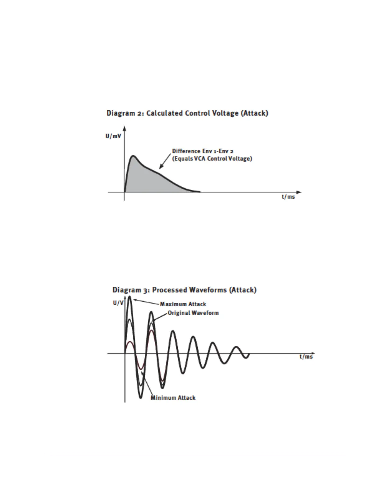
Figure 120 on page 369 shows the difference between Env 1 and Env 2 that
defines the control voltage of the VCA. The shaded area marks the difference
between Env 1 and Env 2 that controls the control voltage of the VCA. The am-
plitude of the attack is increased if positive ATTACK values are set. Negative
ATTACK values reduce the level of the attack transient.
Figure 121 on page 369 displays the processed waveforms with maximum
and minimal ATTACK to compare against the original waveform in diagram
1.
Figure 120. SPL Transient Designer Attack Control Voltage
Figure 121. SPL Transient Designer Processed Attack
 Loading...