Apollo Solo Manual Hardware Controls & Connectors 30
Rear Panel
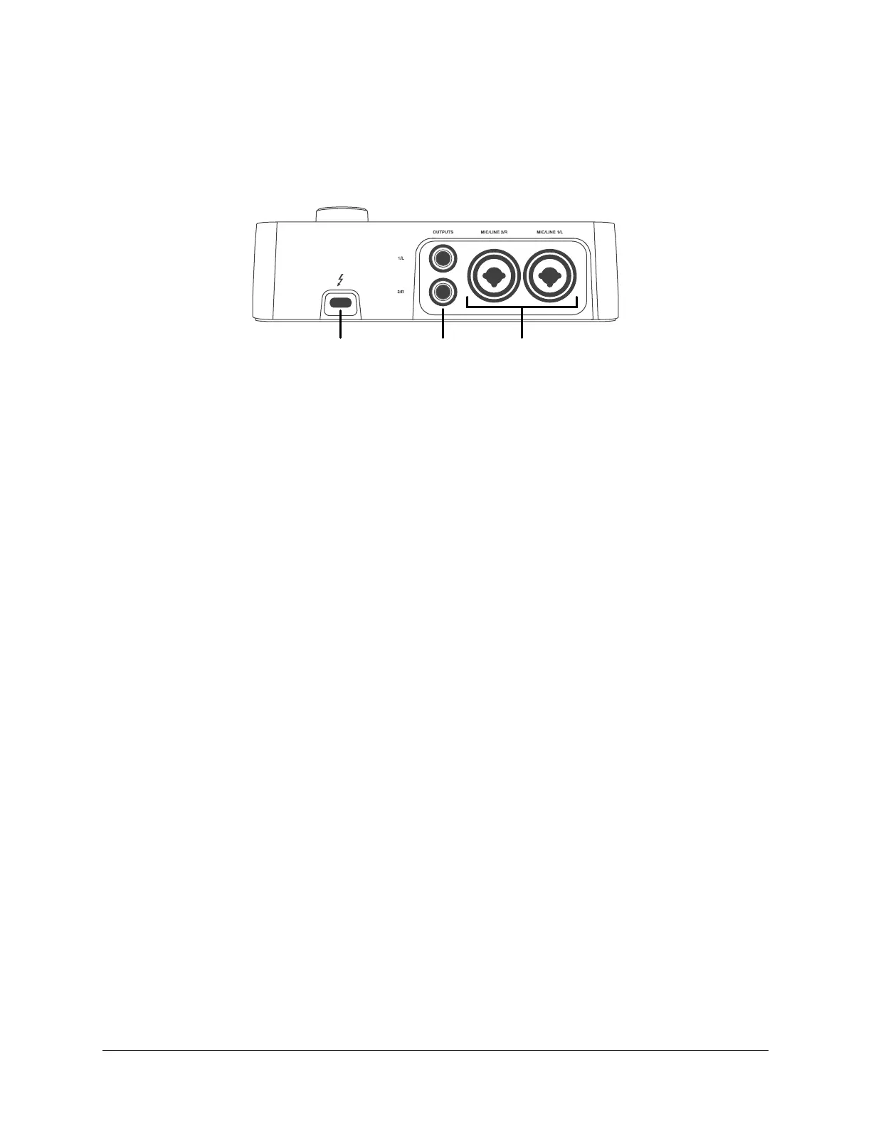
Refer to the illustration below for control descriptions in this section.
Note: All rear panel ¼” jacks can accept unbalanced TS (tip-sleeve) or balanced
TRS (tip-ring-sleeve) connections.
Rear panel connectors
(16) Thunderbolt 3 Port
Connect the Thunderbolt 3 cable (not included) here. A Thunderbolt 3 connection to the
host computer is required to use Apollo Solo.
Thunderbolt 3 Port Notes:
• Apollo Solo requires a built-in Thunderbolt 3 via USB-C port for the computer
connection.
• Although Thunderbolt 3 always uses USB-C connectors, not all USB-C computer
ports are Thunderbolt 3 ports.
• Apollo Solo is incompatible with Thunderbolt 1 and Thunderbolt 2 computer
ports, even if an adapter is used.
• See About Thunderbolt 3 Power and About Thunderbolt 3 Ports and Cables for
related information.
(17) Monitor Outputs
Connect powered monitor speakers (or an amplifier+speaker system) here. Volume is set
with the LEVEL knob (1) when MONITOR is selected (10) with the MONITOR button (3).
Caution: Before powering Apollo Solo, lower the volume of the monitor speakers
and remove headphones from your ears.
(18) Mic/Line Inputs 1 & 2
The female combo jacks for channels 1 & 2 accept either a male XLR plug for
connecting to the mic input, or a ¼” phone plug for connecting to the line input.
The input jack that is used for the channel (MIC or LINE) is specified with the Input
Select button (5-a).
Caution: To avoid potential equipment damage, disable +48V phantom power on
the channel before connecting or disconnecting its XLR input.
16 17 18