2. Dual Robot Calibration
Mean deviation:
The average deviation in millimeters and in milliradians between the positions mea-
sured by the first and second robot
Standard deviation: The standard deviation calculated on basis of the above
Max deviation: The maximal measured deviation
Expected results
The calibration is passed successfully if:
• Mean deviation will be less than 1 mm and 2 mrad
• Standard deviation is less than 0.5 mm and 1 mrad
• The different between the Calibration and Control results is not more than 50% different
2.9 Applying the Calibration
After step no: 16 the calibration is applied to the controller. The calibration is permanently saved after
succesful validation. Then the robots are ready to be disconnected.
(17)
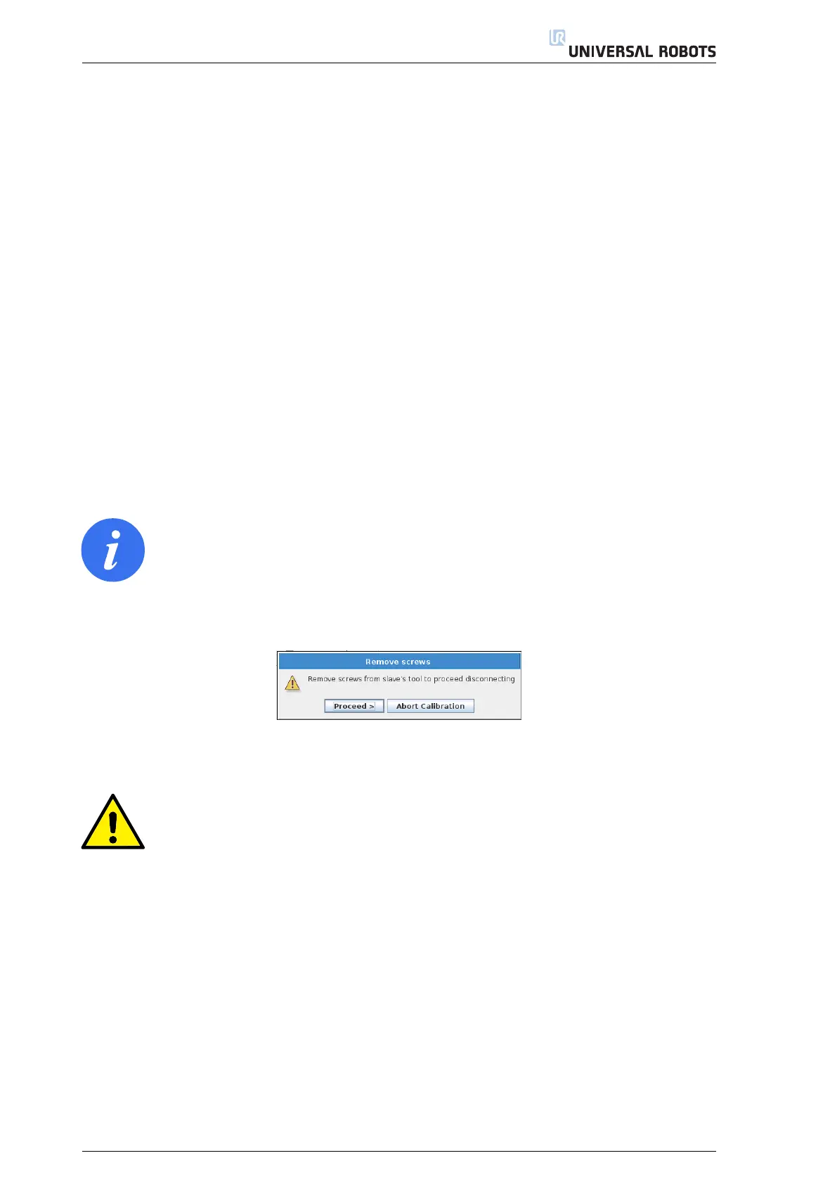
A pop-up appears as shown in Figure 2.27. Dismount the screws from the connector and press Proceed.
If the Auto step box is checked, the robots will continue with correcting the robots’ home position.
NOTE:
If you tap Proceed without removing all of the screws from the tool connector on the slave
robot, each robot can make a protective stop. To resolve the problem, verify all screws are
removed and clear the Protective Stop/s. Once this is done, press Proceed again.
Figure 2.27: Remove screws
CAUTION:
If either robot enters a Protective Stop while disconnecting, you must remove the Tool Con-
nector and jog the robots to separate them manually. Once the robots are separate and the
Protective Stop is cleared, the disconnection dialog box reappears on PolyScope and you can
retry the step.
2.9.1 Validation
Next follows a validation procedure. Here both robot tool flanges need to be completely free from e.g. screws
and alignment pins.
(18)
Remove the Calibration Tool Connector and alignment pins etc. and Proceed with the validation, see
Figure 2.29. The robots TCP will now approach one another.
(19)
Verify that the distance in-between the robot tools is within a distance of 2.5 mm
±
1
mm
using the Go
and No Go tools, see Figure 2.30.
(a) Verify that the 1.5 mm Go tool can pass in-between the two robot’s tool flanges
(Figure A.3, Appendix A)
12