2. Dual Robot Calibration
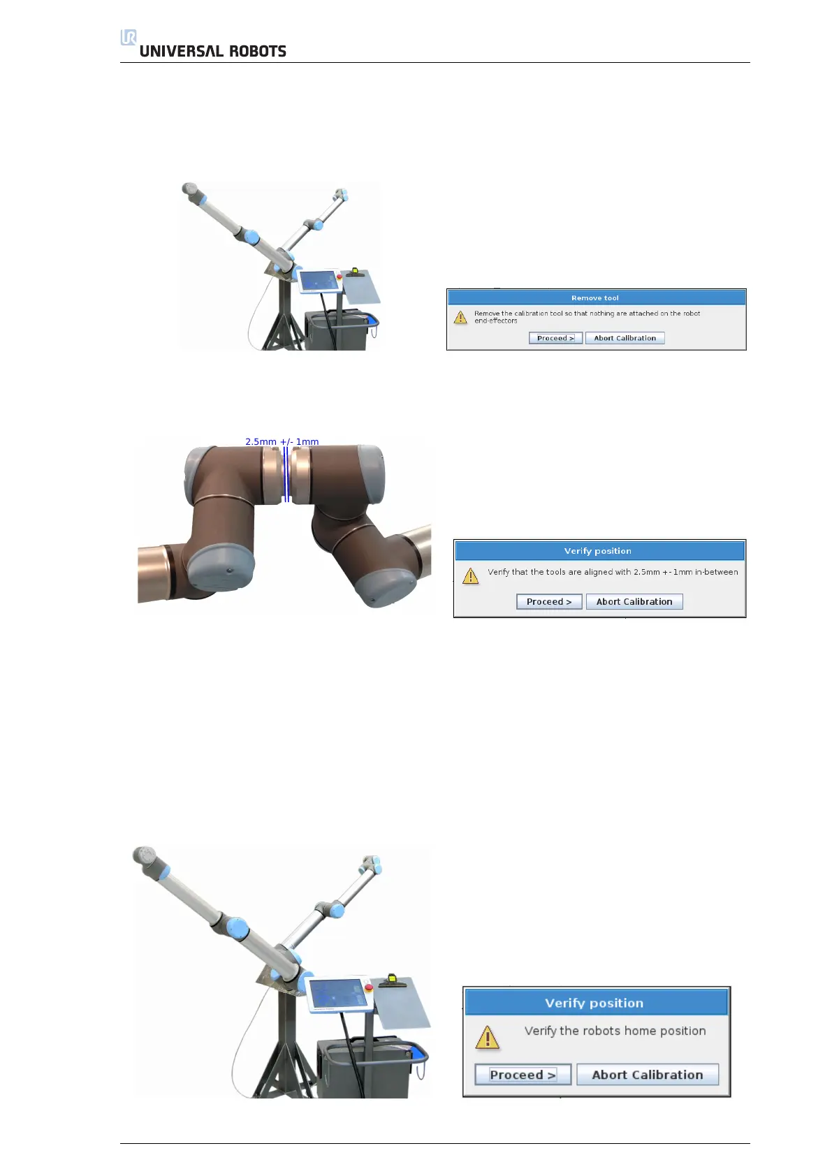
(b) Verify that the 3.5 mm No G o tool can not pass in-beween the two robot’s tool flanges
(Figure A.4, Appendix A)
(20) If the verification is successful in step no. 19, Proceed to the next validation step, see Figure 2.31.
Figure 2.28: Robots ready for the validation procee-
dure
Figure 2.29: Proceed to the Verification procedure
when the Calibration Tool Connector, screws, and
alignment pins are removed from the robots tool
flange
Figure 2.30: Verification by alignment of tools
Figure 2.31: Proceed if the verification in step no. 19
is successful
Secondly the robots will move to their new calibrated home position. Here it is important that the robots
are fully stretch out and that the tools are pointing in the right direction, like in Figure 2.32. After completion
of step no. 22 the Dual Robot Calibration procedure has been completed, see Figure 2.34
(21) Verify the robot home positions, see 2.32.
(22) If the verification is successful in step no. 21, Proceed to the next validation step, see Figure 2.33.
(23) Save the calibration
(24) Calibration done, press Exit, see Figure 2.34.
Figure 2.32: Verify the robots new home position
Figure 2.33: Proceed if the verification in step no. 21
succeed
13