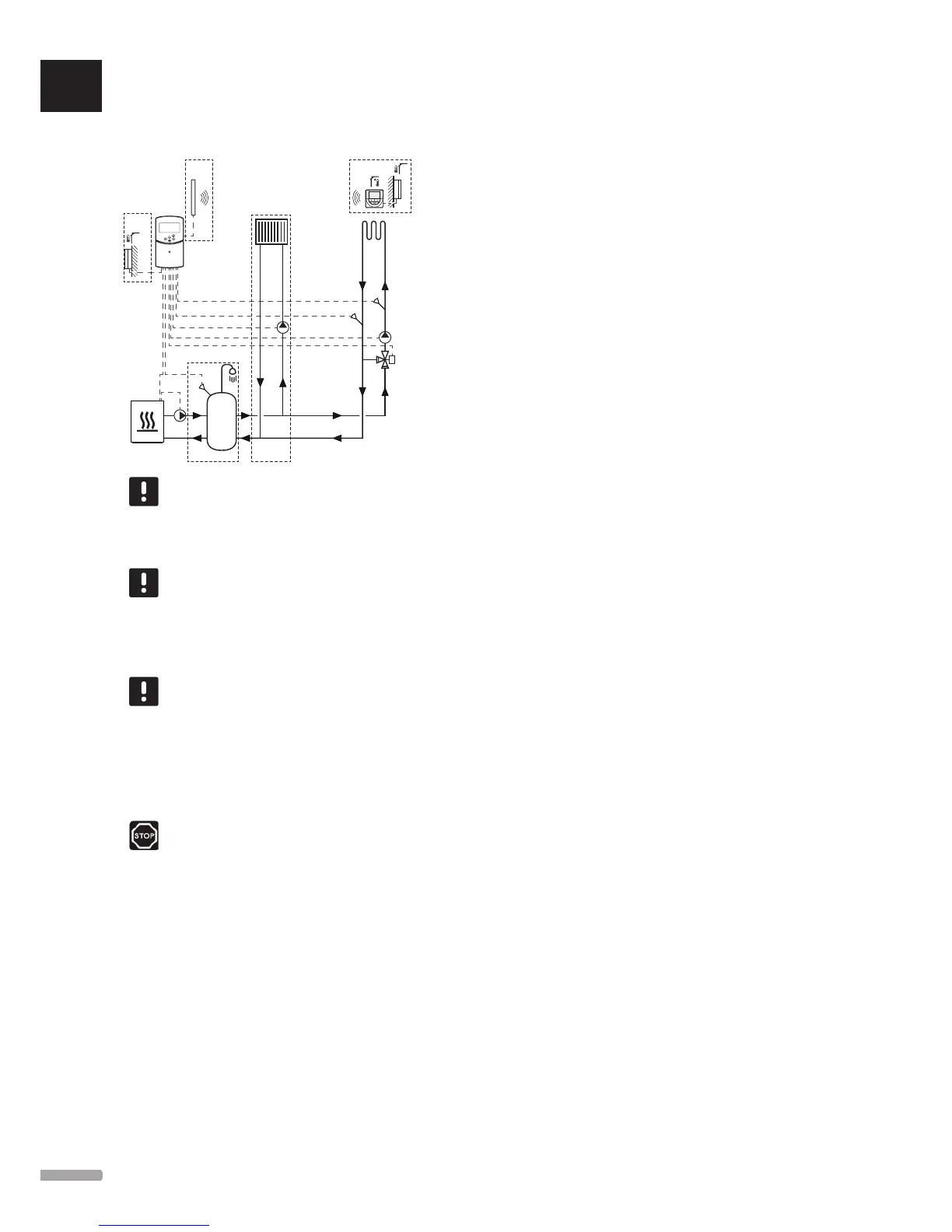
Heating system together with DHWT and
panel heater
Move PLUS
Move
Move PLUS
Option 1
Option 2
Option 3
NOTE!
This is an outline diagram. A real system must
be installed according to applicable norms
and regulations.
NOTE!
If the outdoor sensor is placed to far away
from the reference room (Move PLUS only),
a separate thermostat can be used to register
the outdoor sensor.
NOTE!
When registering a thermostat to the
controller (Move PLUS only), run mode
changes parameter 0 (type) to rEv,
regardless of previous setting. Heating/
cooling is then controlled by the thermostat,
or the integrated system.
Warning!
There is 230 V (5 A) power in the controller
when connected to the mains.
This installation example depicts a heating system with
an optional domestic hot water tank (DHWT) and panel
heater. The system prioritises domestic hot water.
The circulation pump and mixer valve, supplying
the heating system, is operated by the controller to
maintain the supply temperature.
An optional DHWT (option 1) is installed close to the
heat source, with an immersion thermostat/aquastat
connected to the controller.
An optional panel heater (option 2) is installed before
the mixer valve to offer an extra heating system, using
the full capabilities of the heat source. The operation
of the second circulation pump, supplying the panel
heater, can be controlled by an optional extra wireless
thermostat (Move PLUS only).
An optional return temperature sensor (option 3), is
in a Move system connected the controller to speed
up the reaction of the system. This is achieved using
a boost parameter to adjust the calculated supply
temperature, if the difference between supply and
return temperatures is to large.
Example specific electrical connections
• The circulation pump, supplying the heating system,
is connected to the terminal labelled P1.
• The circulation pump, supplying the optional panel
heater, is connected to the terminal labelled P2/
COLD.
• The mixer valve actuator, supplying the heating
system, is connected to the terminal labelled
ACTUATOR.
• The immersion thermostat/aquastat is connected to
the terminal labelled ROOMSTAT (terminal In1 or
In2).
• The optional return temperature sensor is connected
to the terminal labelled WATER RETURN.
See section 5.4 Connect components to controller for
more information.
See also the wiring diagram in the end of the manual.
Example specific system parameter settings
• Set parameter 0 – Type of installation to Hot if it is
a heating system.
• Set parameter 4 – Type of system to 2P.1 if the
circulation pump supplying the optional panel
heater is installed.
• Set parameter 5 – Thermostat selection to no (to
utilise the boost function) The boost function can
only be used in systems with a return sensor, and
without a wireless thermostat).
• Set parameter 7 – Boost function to an appropriate
value, for the system (requires parameter 5 being
set to no and is used in systems with a return
sensor, and without a wireless thermostat).
• Set parameter 11/12 – Wired input 1/2 selection
to Aqu if an immersion thermostat/aquastat
is installed in the tank, and connected to the
controller.
See section 8.6 System parameter settings for more
information.
See section 6.9 Register thermostats to the controller for
more information about registering a thermostat to the
Move PLUS controller.
UK
CZ
DE
DK
EE
ES
FI
FR
HR
HU
IT
LT
LV
NL
NO
PL
PT
RO
RU
SE
SK
16
UPONOR SMATRIX MOVE/MOVE PLUS · INSTALLATION AND OPERATION MANUAL