Free cooling together with a heat
pump in a combined heating/cooling
system
EPG
NOTE!
This is an outline diagram. A real system must
be installed according to applicable norms
and regulations.
Warning!
There is 230 V (5 A) power in the controller
when connected to the mains.
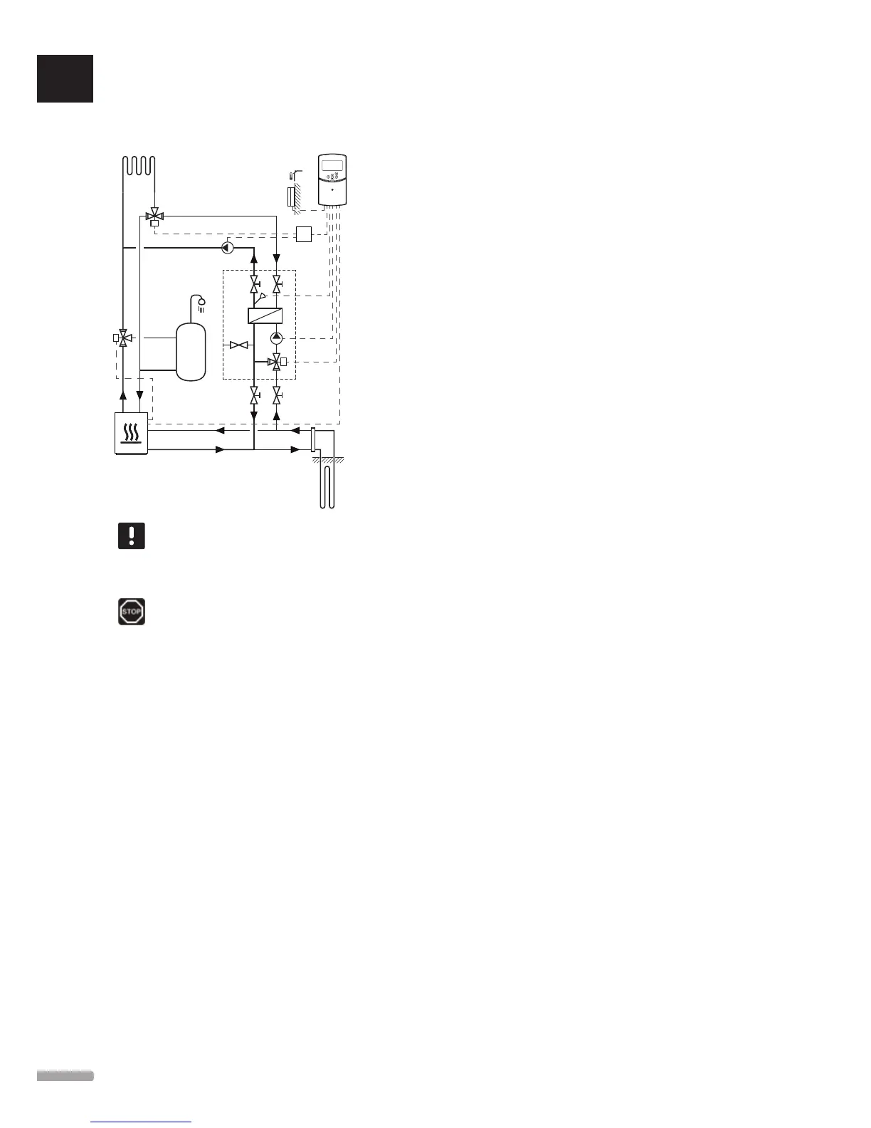
This installation example depicts a combined heating/
cooling system where a heat pump produces heating
and hot water, and an Uponor pump group (EPG)
supplies the system with free cooling. For best per-
formance, upgrade the Move system to Move PLUS.
The pump group (EPG) consists of a brine circulation
pump, a 3-way valve with an actuator, temperature
gauges, closing valves, and a heat exchanger. The EPG
is controlled by an integrated Uponor Smatrix Move
controller.
The integrated Move controller also controls the
external circulation pump supplying the heating/
cooling system with free cooling and a 3-way valve, for
switching between heating and cooling.
The heat pump has internal circulation pumps for
heating, hot water and brine.
When a cooling demand emerge, the heat pump sends
(or another device, such as a switch) a signal to the
EPG. The integrated Move controller switches over the
3-way valves and starts the circualtion pumps to start
producing free cooling. When the system is in cooling
mode, the heat pump also can produce domestic hot
water.
Example specific electrical connections
• The EPG brine circulation pump, is connected to the
terminal labelled P1.
• The EPG supply temperature sensor, is connected to
the terminal labelled WATER IN.
• The EPG 3-way valve actuator, is connected to the
terminal labelled ACTUATOR.
• The external cooling circulation pump, supplying
the heating/cooling system, is connected to a
junction box, in turn connected the terminal
labelled P2/COLD.
• The external 3-way valve actuator, switching the
system between heating and cooling, is connected
to a junction box, in turn connected the terminal
labelled P2/COLD.
• The heat pump heating/cooling signal is connected
to the terminal labelled ROOMSTAT (terminal In1
or In2).
See section 5.4 Connect components to controller for
more information.
See also the wiring diagram in the end of the manual.
Example specific system parameter settings
• Set parameter 0 – Type of installation to rEv if it is a
heating/cooling system.
• Set parameter 2 – Maximum supply temperature
(heating) to 11 ˚C to avoid the cooling from
interfering with the primary heat production.
• Set parameter 3 – Minimum supply temperature
(heating) to 5 ˚C to avoid the cooling from
interfering with the primary heat production.
• Set parameter 4 – Type of system to Act if the
external 3-way valve and circulation pump is
installed.
• Set parameter 5 – Thermostat selection to no (to
utilise the boost function) The boost function can
only be used in systems with a return sensor, and
without a wireless thermostat).
• Set parameter 7 – Boost function to an appropriate
value, for the system (requires parameter 5 being
set to no and is used in systems with a return
sensor, and without a wireless thermostat).
• Set parameter 11/12 – Wired input 1/2 selection
to HC if a heat pump heating/cooling signal is
connected to the controller.
See section 8.6 System parameter settings for more
information.
UK
CZ
DE
DK
EE
ES
FI
FR
HR
HU
IT
LT
LV
NL
NO
PL
PT
RO
RU
SE
SK
18
UPONOR SMATRIX MOVE/MOVE PLUS · INSTALLATION AND OPERATION MANUAL