Section
3-23AB46 Work Platform
Maintenance
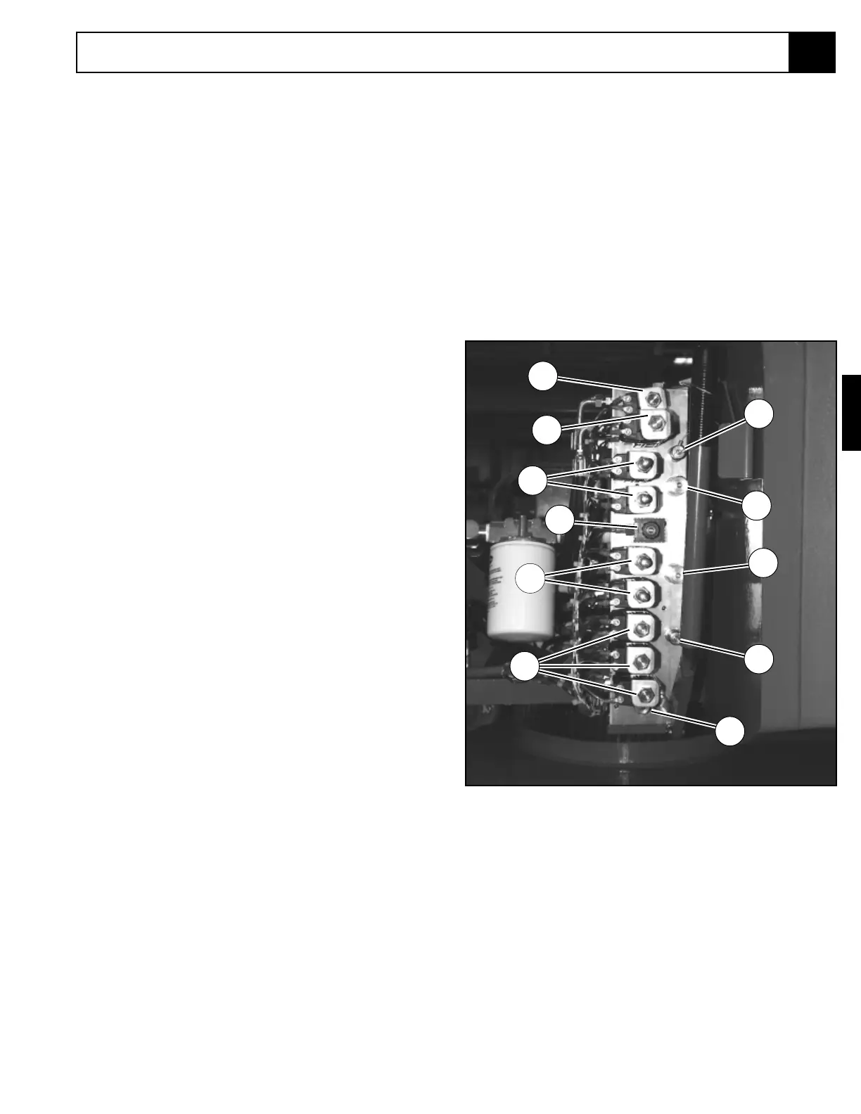
Figure 3-23: Valve Manifold
3.14 Setting Hydraulic Pressures
Figure (3-8) shows complete hydraulic manifold
assembly.
Note: Check hydraulic pressures whenever the
pump, manifold or any relief valve has been serviced
or replaced.
HIGH RELIEF VALVE (Figure 3-23)
1. Operate the hydraulic system 10-15 minutes to
warm the oil.
2. Remove the high relief port plug and install a 0-
3000 PSI pressure gauge assembly.
3. Remove the plug in the end of the high relief valve
to expose the adjusting screw.
4. Operate Jib raise function until jib is completely
raised.
5. While activating the jib raise switch, set the pressure
to 2500 PSI (173 bar) maximum by slowly turning
the adjusting screw. Turning the adjusting screw
clockwise increases pressure and counterclockwise
decreases pressure.
6. Remove the pressure gauge and reinstall all plugs.
LOW RELIEF VALVE
1. Operate the hydraulic system 10 - 15 minutes to
warm the oil.
2. Remove the low relief port plug and install a 0-3000
PSI pressure gauge assembly.
3. Remove the plug in the end of the low relief valve
to expose the adjusting screw.
4. Turn the low relief valve adjustment screw counter-
clockwise two full turns.
5. Operate jib lower function until jib is completely
lowered.
6. While activating the jib lower switch, set the pres-
sure to 1500 PSI (104 bar) maximum by slowly
turning the adjusting screw. Turning the adjusting
screw clockwise increases pressure and counter-
clockwise decreases pressure.
7. Remove the pressure gauge and reinstall all plugs.
1. Motor Spool 4 way Valve, 3 position
2. Closed Center 4 way Valve, 3 position
3. Tandem Center 4 way, 3 position Valve
4. Low Flow Valve
5. High Flow Valve
6. Counterbalance Valve
7. Low Relief Gage Port Plug
8. Low Relief 1500 PSI
9. High Relief 2500 PSI
10. High Relief Gage Port Plug
COUNTERBALANCE RELIEF
VALVES
1. If any counterbalance relief valve is faulty, com-
pletely lower the jib, boom and elevating assembly
and replace the counterbalance valve.
2. Replace or recalibrate (bench set) the counterbal-
ance valve.
3. Slowly cycle function related to replaced counter-
balance valve several times to remove air from
system.
9
10
5
3
2
4
2
1
8
7
6
3.14
 Loading...