Contents
i
Section
IV AB46 Work Platform
List of Tables
Figure Page
No. Title No.
1-1 Specifications............................................................ 1-2
3-1 Preventative Maintenance Checklist .................... 3-2
3-3 Bolt Torque ............................................................... 3-32
3-4 Hydraulic Component Torque.............................. 3-32
4-1 Troubleshooting Guide-Hydraulics ..................... 4-2
4-2 Troubleshooting Guide-Electrical......................... 4-4
5-1 Electrical Schematic Legend, Gasoline Model.... 5-2
5-2 Electrical Schematic Legend, Dual Fuel............... 5-4
5-3 Electrical Schematic Legend, Diesel ..................... 5-6
5-4 Hydraulic Schematic Legend................................. 5-8
5-5 Upper Controller Components ............................. 5-14
5-6 Lower Controller Components ............................. 5-16
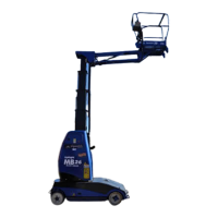
1-1: AB46 Work Platform............................................... 1-1
2-1: Chassis Controls ...................................................... 2-3
2-2: Platform Controls .................................................... 2-3
2-3: Fall Restraint Ancorage Point................................ 2-3
2-4: Emergency Control Operation .............................. 2-6
2-5: Manual Turret Rotation.......................................... 2-6
2-6: Securing the Machine for Transportation............ 2-7
2-7: Fuel Fill Pipe/Level Gauge .................................... 2-8
2-9: Hydraulic Oil Filler ................................................. 2-8
3-1: Blocking Elevating Assembly ................................ 3-3
3-2: Lubrication Chart .................................................... 3-5
3-3: Proportional Controller .......................................... 3-6
3-4: Rotary Control Adjustment ................................... 3-6
3-5: Proportional Control Adjustment......................... 3-7
3-6: Platform Down Limit Switch................................. 3-7
3-7: Tilt Sensor ................................................................. 3-8
3-8: Hydraulic Manifold, Exploded View................... 3-9
3-10: Rear Axle Assembly................................................ 3-10
3-11: Brake Assembly ....................................................... 3-11
3-12: Pressure Override Valve ........................................ 3-12
3-13: Hydraulic Pump ...................................................... 3-12
3-14: Front Axle Assembly .............................................. 3-13
3-15: Drive Motor.............................................................. 3-14
3-16: Torque Hub .............................................................. 3-15
3-17: Torque Hub Assembly............................................ 3-16
3-18: Measuring Hub End Play....................................... 3-18
3-19: Torque Hub .............................................................. 3-19
3-20: Seal Pressing Tool.................................................... 3-20
3-21: Bearing Cone Pressing Tool ................................... 3-21
3-22: Bearing Cup Pressing Tool..................................... 3-22
3-23: Valve Manifold ........................................................ 3-23
3-24: Master Cylinder ....................................................... 2-24
3-25: Slave Cylinder .......................................................... 3-25
3-26: Cage Rotate Cylinder.............................................. 3-26
3-27: Steering Cylinder..................................................... 3-27
3-28: Jib Cylinder............................................................... 3-28
3-29: Boom Raise Cylinder .............................................. 3-29
3-30: Removing Boom Extend Cylinder........................ 3-30
3-31: Boom extend Cylinder............................................ 3-31
List of Illustrations
Table Page
No. Title No.
5-1: Electrical Schematic, Gas Model ........................... 5-3
5-2: Electrical Schematic, Dual Fuel ............................. 5-5
5-3: Electrical Schematic, Diesel.................................... 5-7
5-4: Hydraulic Schematic............................................... 5-9
5-5: Valve Block Assembly ............................................ 5-10
5-6: Hydraulic Valve Ports ............................................ 5-11
5-7: Check Ports............................................................... 5-12
5-8: Drive Valve Block.................................................... 5-13
5-9: Upper Controller ..................................................... 5-14
5-10: Electrical Diagram, Upper Control Box, Gas...... 5-15
5-11: Electrical Diagram, Upper Control Box, Diesel.. 5-15
5-12: Lower Control Box Cover ...................................... 5-16
5-13: Terminal Strip, Relay Identification ..................... 5-16
5-14: Electrical Diagram - Lower Control Box, Gas .... 5-18
5-16: Electrical Diagram - Lower Control Box, Diesel 5-19
Figure Page
No. Title No.
List of Illustrations (continued)
 Loading...