Batteries Section 2 - Service and Repair
Page 2-8 113101-000 MX15 / MX19 | Service Manual
B
ATTERY
R
EPLACEMENT
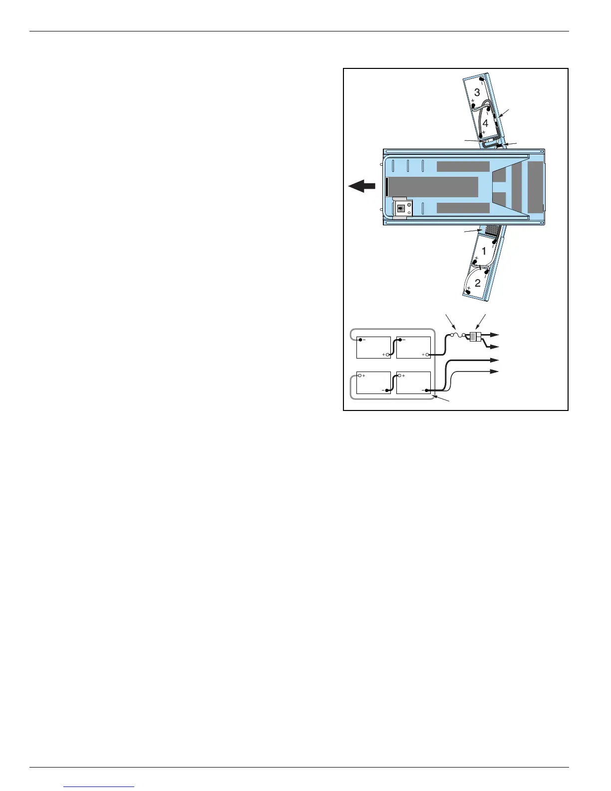
Figure 2-3:
Battery Cables
There are two batteries located in each door. The
four 6 volt batteries are wired in series for 24 volts
DC. Battery cables must be installed as shown in the
Battery Cable Installation Diagram.
R
EMOVAL
1. Turn the Chassis Key Switch to the OFF position
and push the Chassis and Platform Emergency
Stop Switches down to the OFF position.
NOTE:
If switches are ON, a spark may occur at the negative
lead which could cause an explosion if hydrogen gas or
fuel vapors are present.
2. Open the right-side door and disconnect the bat-
tery pack connector.
3. Open the left-side door and disconnect the battery
negative (–) lead on battery #1.
IMPORTANT: Disconnect the battery negative (–) lead on
battery #1 first.
4. Disconnect the remaining battery leads.
5. Lift the batteries out of the doors.
I
NSTALLATION
NOTE:
Replacement batteries must be equal to or greater than
the weight of the originals to maintain stability when the platform is elevated. Always replace batteries with UpRight
batteries or manufacturer approved replacements weighing 26,3 kg (58 lb.) each.
Battery cables must be installed as shown in Figure 2-3.
1. Verify that the Chassis Key Switch and the Chassis and Platform Emergency Stop Switches are in the
OFF position.
2. Place the batteries into the doors as shown in Figure 2-3.
3. Connect the battery to battery leads.
IMPORTANT: Connect the battery negative (–) lead on battery #1 last.
4. Connect the battery pack connector.
Battery #2 Battery #1
Battery #3 Battery #4
Charger
Fuse
RIGHT DOOR
LEFT DOOR
Front
Fuse
Controller (B –)
Charger
Motor Relay
Controller (B +)
Motor Relay
Battery Connector
Battery Connector
Negative Lead
 Loading...


