13
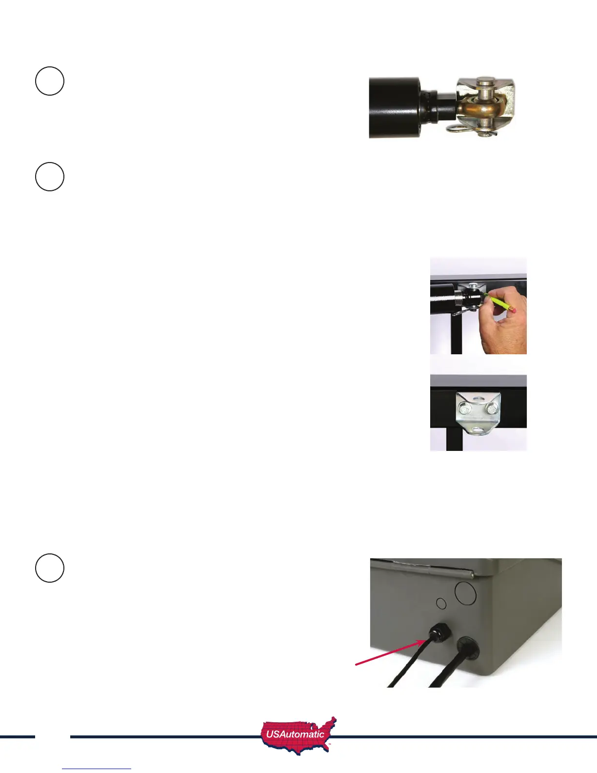
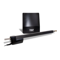
Install Gate Bracket to Linear Actuator
Installmanualreleasepin,gatebracketandmanual
releasecliptolinearactuatorextensionrodend.
Install Gate Bracket to Gate (Pull to Open Only)
To determine where the gate bracket will be installed follow these steps: The linear actuator
should be connected to the actuator bracket at this point. NOTE - The linear actuator was shipped
from the factory set to the fully retracted position.
1. Swinggatetothefullyopenposition.
2. Nowopengateanothercoupleofinches(thegatewillneveropen
morethanthisposition).Thegatecanbeadjustedlatertoopena
little less if needed.
3. Swinglinearactuatoraround(shouldswingfreely)inalevelposition
tomeetthefullyopengate.Thisiswhereyoushouldinstallthegate
bracketonthegate.
4. Markthelocationofthe1/4”holesforthemountingbracket.(see gure)
5. Removepinandclipfrombracket.
6. Attachbrackettogate(ifusingalightweighttubularfarmgateusegate
supportbracketforsupport).Usethe1/4”x21/2”or31/4”tapbolts
dependingongatethickness,four1/4”atwashersandtwo1/4”nylon
locknuts.Tightensecurely.
7. Attachactuatortothenowsecuredgatebracketusingmanualreleasepin
andclip.
8. Thegateshouldnowbefullyopenedwiththeactuatorattached.
9. Verifythatlinearactuatorislevelandallpieceshavebeen
installedcorrectly.
Installing Gate Bracket to Gate for Push to Open configuration
ProcedureisidenticaltothestepsforPulltoOpenexceptthegatewillbeinthefullyclosedposition.
Forapushtoopenconguration,youwillneedtoreversetheoperatingdirectionforthegateonthe
controlboard.
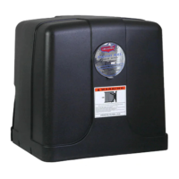
Preparing Sentry Control Box
for Installation
Thecontrolboxhastwoholesinthebottomofthebox
providingaccesstothewirecompartment.Thelargehole
isfortheactuatorcableandthesmallerholeisforthe
chargedevicecable.
Installtheprovidedcableglandintothesmall
hole as shown here.
Cable
Gland
6
7
8