14
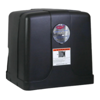
Install Sentry Control Box
Thecontrolboxshouldbeinstalledinalocationthatwillnotrequire
theeightfootlinearactuatorcabletobespliced.Ifthecablemustbe
spliced,refertothesplicinginstructionsbelow.Themostcommon
locationwouldbeonafenceorwalladjacenttoyourgate.Avoid
placingthecontrolboxbehindsolidmetalobjectsthatmightinterfere
withthereceiverreception.Theantennaforthereceiverislocated
insidethecontrolboxandthiscouldreducetheoperatingrange.
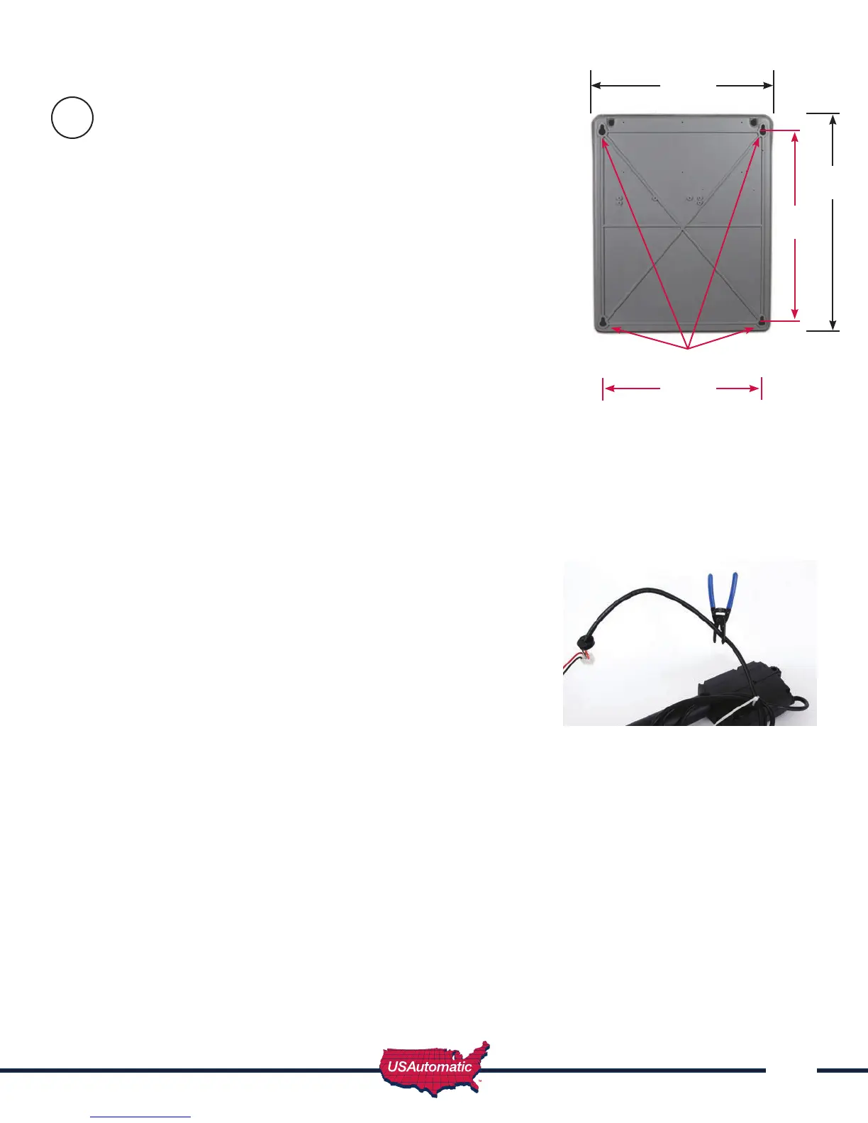
1. Usecontrolboxasatemplatetodetermineandmarkthe
mountingscrewlocationsusingthe4mountingholesshownin
gurehere.
2. DrillmountingholesforscrewsDONOTATTEMPTTO
HOLDTHECONTROLBOXINPLACEWHILEYOU
DRILLTHEMOUNTINGHOLES.Thiscoulddamage
thepreinstalledcomponents.
3. Attachthe4#12hexheadselftappingmetalscrews.
4. Mountthecontrolboxonthescrews.
Verify the structure the control box is mounted on is sufcient enough
to hold the control box and battery securely.
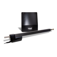
Splicing for Sentry 300 S Linear Actuator Cable (if needed)
TheSentrylinearactuatorcomeswith8feetofcable.Avoidsplicing
thiscableifpossible.Ifthecontrolboxmustbelocatedinsucha
waythatsplicingisrequiredfollowtheguidelinesbelowtoavoid
problems.Determinethelengthofadditionallinearactuatorcable
neededandeitherbuildityourselforvisitwww.sentrygateopener.
comfororderingthelengthofextensioncableneeded.
1. Locatethelinearactuator8pinconnector.Measure18”from
connectorandmark.
2. Cutcableatthe18”mark.Thiswillallowenoughcabletobesplicedandplacedinthewire
compartment.
3. Bringextensioncableintocontrolboxandsplice5wiresusingwirenuts.
4. Useapprovedweathertightelectricaljunctionboxforthesplicelocatedoutsidethecontrolbox.
5. Conduitshouldbeusedbetweenjunctionboxandcontrolbox.Controlboxknockoutisfor
1/2”conduit.
6. Theextensioncablemustconsistof5wires,2fourteengaugewiresand3eighteengaugewires.
•Redwirewithwhitestripe–14gauge(distanceaddedisgreaterthan50feetuse12gauge)
•Blackwirewithwhitestripe–14gauge(distanceaddedisgreaterthan50feetuse12gauge)
•Orangewire–18gauge(distanceaddedisgreaterthan50feetuse16gauge)
•Greenwire–18gauge(distanceaddedisgreaterthan50feetuse16gauge)
•Whitewire–18gauge(distanceaddedisgreaterthan50feetuse16gauge)
7. Withextensioncablenowinthejunctionboxstripandpreparetosplicetolinearactuatorcable.
8. Routelinearactuatorcableintojunctionboxandspliceusingwirenuts.
NOTE: Cable splice must be water tight to keep moisture away from splices and prevent problems
Mounting Holes 4 Places
9
14.25”
17.7”
11.7”
14.5”