26
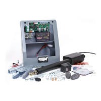
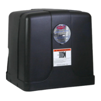
TheGate2kitcontainslinearactuatorwith11/4”holeplug,50feetof5conductor
cable,wirenuts,junctionboxandmountinghardware.TheSentrycontrolbox
isequippedwithtwoknockoutsforthegate2linearactuatorcable.Oneknock
outis11/4”andisintendedfornonconduitinstallation(notadvised).Theother
knockoutis7/8”anddesignedfor1/2”conduitttingforconduitinstallation
(recommended). (see gure)
Ifconduitisbeinginstalledknockout7/8”hole.Ifconduitisnotbeinginstalled
knockout11/4”hole.
Removetheknockoutthatisrightforyourinstallation.
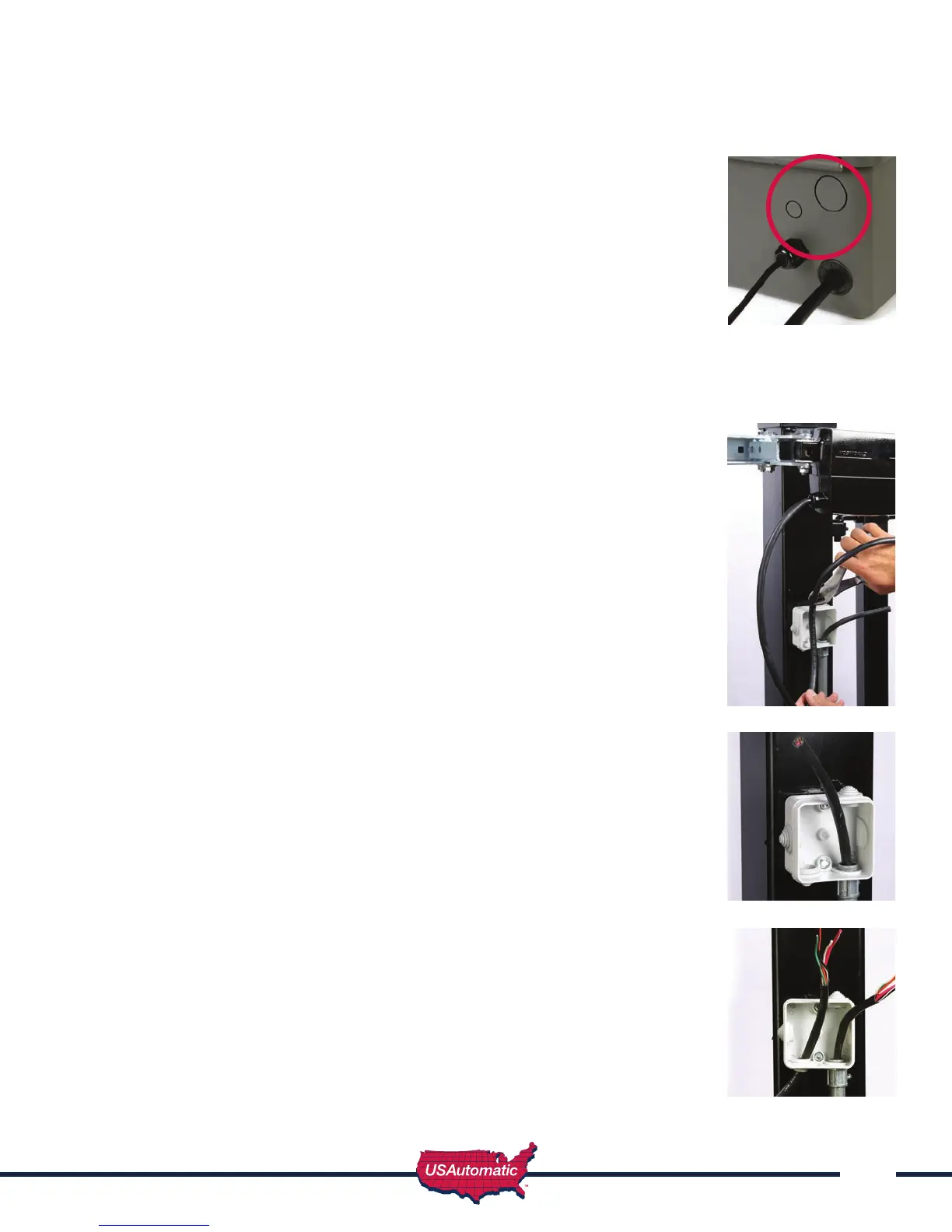
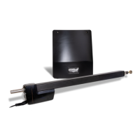
Installing Gate 2 Linear Actuator
1. InstallGate2linearactuatorusingtheproceduredescribedfortheGate1actuator.
The linear actuator for Gate 2 comes with an 8’ cable that must be cut and
spliced in the following manner once linear actuator is installed.
Once Actuator is installed:
1. Locatethelinearactuatorcableconnectorandmeasure18”fromconnector
endandcut(see gure).
2. Savethis8pinconnectorandpigtailforstep21onnextpage.
3. InstalljunctionboxonGate2hingepostbelowlinearactuatorusingthe2self
tappingmetalscrews.
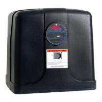
NOTE: Sentry 300 D Gate 2 kit includes 50’ of extension cable, if
distance between control box and junction box exceeds this distance
it is recommended to purchase a cable that will not require additional
splices in the cable. Visit web page to order Sentry 300 D Gate 2
extension cable www.sentrygateopener.com.
4. Ifconduitisbeinginstalledattach1/2”conduitadaptertothecontrolbox7/8”knockout.
5. Routelinearactuatorcabletojunctionboxanddeterminelengthneeded(see
gure).
6. Cutcablelongerthanneededforfutureconsiderations(seegure).
7. Remove2”ofcableinsulationtoexposethe5wires.
8. Caution:Donotdamageinternalwires.
9. Removeapproximately1/2”ofinsulationfromeachwire.
10. Ifinstallingconduitattach1/2”adaptertojunctionbox.Ifnot,cut
rubberknockout(supplied)totcable.
11. InstallGate2extensioncableintothejunctionbox(seegure).
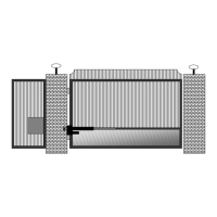
12. Usingsuppliedwirenutsconnectthe5wiresmatchingthewirecolors(see
gure).
13. Donotinstalljunctionboxcoveruntilallconnectionshavebeencompleted
14. Withextensioncablenowinstalledinjunctionbox,routetheotherendofthe
extensioncabletothecontrolbox.
15. Installwiresintocontrolboxwirecompartment.
16. Snap11/4”holeplugintocontrolboxifconduitwasnotused.
Control Box Knock Outs