29
Sentry Photo Eye (Sendandreceive)
PartNumber550012
Thephotoeyeisasecondarysafetydevice.Itproduces
abeambetweenthe2units.Whenthebeamisbroken
itwillkeepthegatefromclosing.Itrequireswiresto
beconnectedtobothunits(20gauge)foroperation.
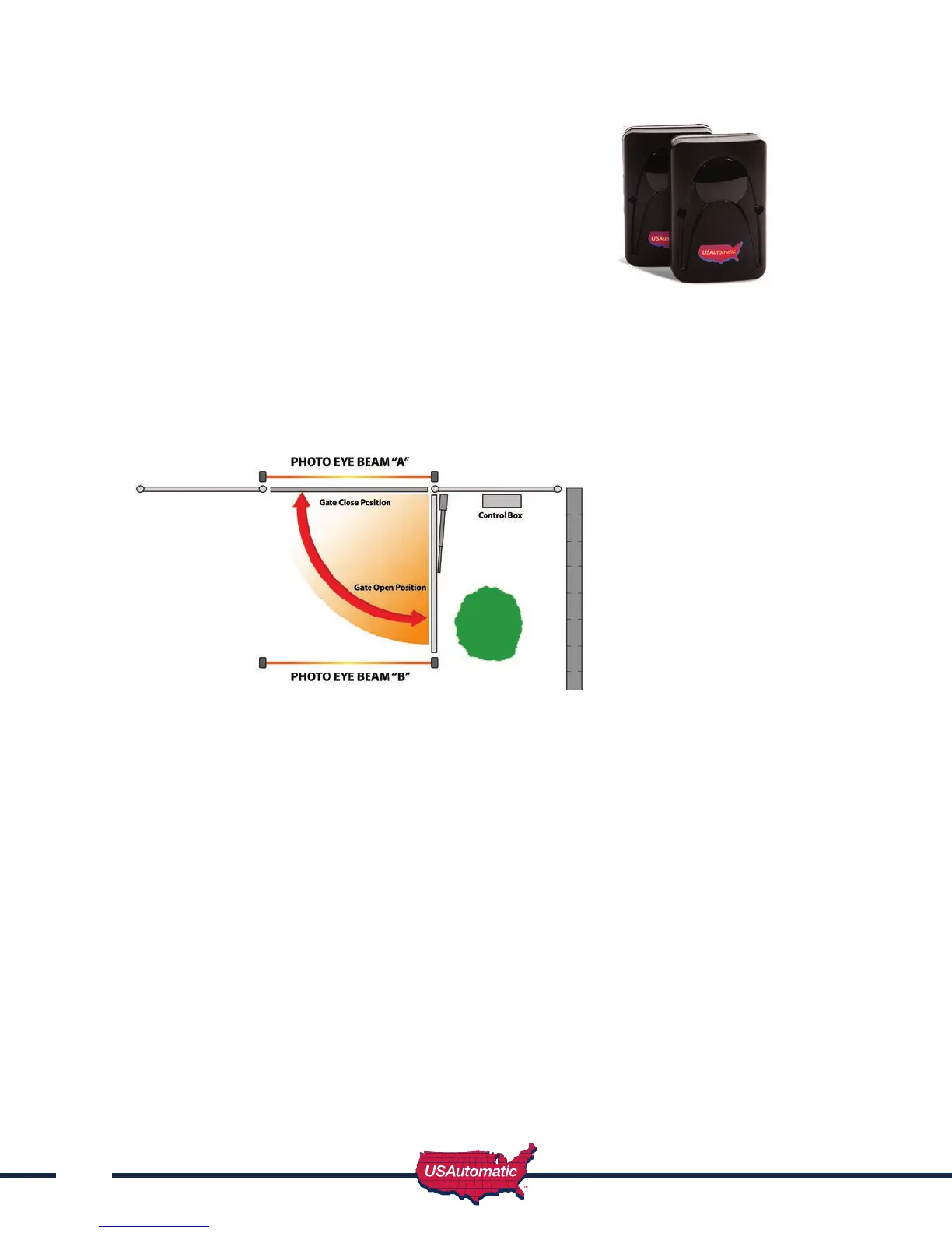
Typicallyaswinggateneedstwosetsofphotoeyesfor
thebestareaprotection(seegurebelow).
Onesetofphotoeyespointingacrossthedriveonthe
outsideofthehingepost(A).Thesecondsetmounted
acrossthedriveatthepointwherethegateisfully
opened(B).Thephotoeyemustbeinstalledwherethegatedoesnotbreakthebeam.
Theprimaryunit(Receiver)shouldbeinstalledclosetothecontrolbox.
Itrequires4wirestobeinstalledfromtheunittothecontrolbox.
Thesecondunit(Transmitter)shouldbeinstalledontheoppositesideofthedrive.
Itrequires2wirestobeinstalledfromtheunittothecontrolbox.
Thetwounitsmustfaceeachothertoestablishthebeam(maximumdistance40feet).
Photo Eye Installation / Wiring
Selectaproperinstallationsite,wherethetransmitterandthereceivercanbealongthe
samelineandatthesameheight.Removethecoverfrombothunits.Attachbackplatetothe
installationsiteusingmountingholesinbackplate.
Ifconduitisbeingused(recommended)knockoutsareprovidedintheunitfor1/2”conduittting.
Installwiresintounitandstrip1/4”ofinsulationtoprepareforwiringconnections.
Connectbothconduitstoaweathertightjunctionbox.Thenconnectanadditionalconduit
betweenthejunctionboxandSentrycontrolbox.TheSentrycontrolboxhasknockoutsfor
theconduit.Verifywhichknockoutisavailableforthephotoeyeconduit.PullwireintoSentry
controlboxwirecompartment.
Transmitterwiring–2wireswillbeconnectedtothetransmitter.
Firstwireconnectstoground(“GND”)terminalandthesecondwireconnectsto“+12V”
terminal.
Receiverwiring–4wireswillbeconnectedtothereceiver.
Firstwireconnectsto“+12V”terminal,secondwireconnectsto“NO”terminal,thirdwire
connectstothe“GND”terminalandthefourthwireconnectstothe“COM”terminal.
ConnectthesewirestotheSentryControlboardasfollows:
+12V– J2pin6 (2wiresonefromeachunit)
GND– J2pin2 (2wiresonefromeachunit)
COM– J2pin2 (1wirefromreceiverunit)
NO– J2pin5 (1wirefromreceiverunit)
NOTE:Sentrycontrolboardswitch#6mustbeturned“ON”.
Transmitter Receiver