Chapter 3: Controls and Features
UT100 Handheld Pulse Oximeter Operation Manual 3-1
Chapter 3: Controls and Features
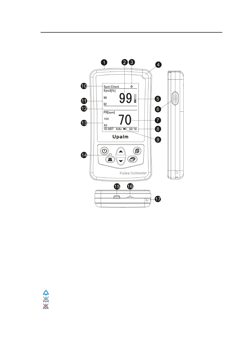
3.1 Monitor Front Panel
Figure 3.1: Monitor
C
on
tr
ols
,
and
F
ea
tures
1. Sensor Connector
The
sensor connects
her
e
,
or an oximetry extension cable can be
connected
between
the
monitor and the
sensor
.
2.
SpO
2
Numeric
D
ispla
y
A number shows the patient’s SpO
2
value in percent. Dashes (- - -) mean the
monitor is not able to calculate the SpO
2
value.
3. Mute icon
The mute icon is displayed at the status bar and it has three statuses:
“ ” this icon means the normal status of pulse/alarm sound.
“ ” this icon is displayed during temporary two-minute pulse/alarm silence.
“ ” this icon is displayed steadily during permanent pulse/alarm silence.