ENGLISH
OPERATION END-STOP
Versions WITHOUT electrical end-stop
For the end-stop operation, proceed as follows:
• Bring the shutter in position of maximum opening,
then position the mechanical stop A, and shot effect,
against the crosshead nut.
• Block the mechanical stop by fastening the bolt with a
13mm key.
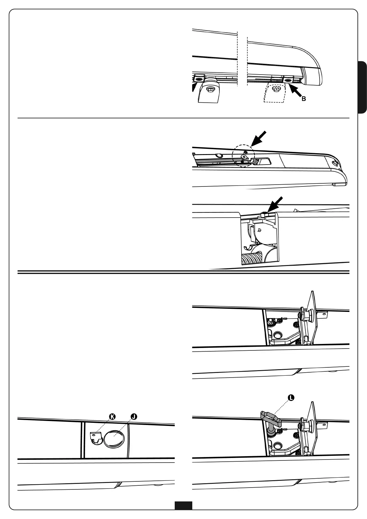
• Bring the shutter in position of maximum closing,
then position the mechanical stop B (accessory code
162223), and shot effect, against the crosshead nut.
• Block the mechanical stop by fastening the bolt with a
1
3mm key.
Versions WITH electrical end-stop
T
he electrical end-stop (already wired inside the motor)
interrupts the feeding on the motor preventing
unnecessary stress and overheating.
For the end-stop operation proceed as follows:
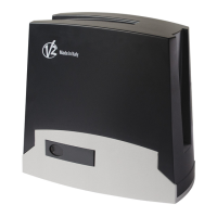
• Remove the front crankcase of the motor and loosen
the assembly nut that holds the electrical end-stop
• Bring the shutter in position of maximum opening and
position the electrical end-stop so that the switch
engages.
• Close the assembly nut that holds the electrical
end-stop
• Insert the front Carter (casing), close the feed screw
and insert plugs
• Position the mechanical stop so that the run is
immediately blocked after the engaging of the switch.
• Block the mechanical stop by fixing the bolt with a
13mm key.
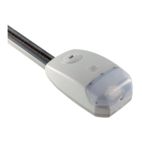
EMERGENCY RELEASE
In case of lack of electrical power, or loss of power,
bypassing the motor can unblock the gate:
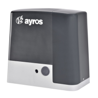
1. Open the closing cover J located on the front side of
the motor
2. Insert key K in the lock, turn it clockwise and
completely open the plastic access flap
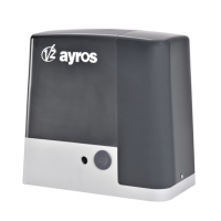
3. Insert key L in the hole and rotate clockwise until
end-stop
In order to restore the automation proceed as follows:
1. Turn the key L in counter-clockwise sense until
end-stop and remove it
2. Close the access flap and turn the key K in
counter-clockwise sense
3. Cover the lock with the access flap J
19