INSTALLATION INSTRUCTIONS vacon • 61
24-hour support +358 (0)201 212 575 • Email: vacon@vacon.com
8
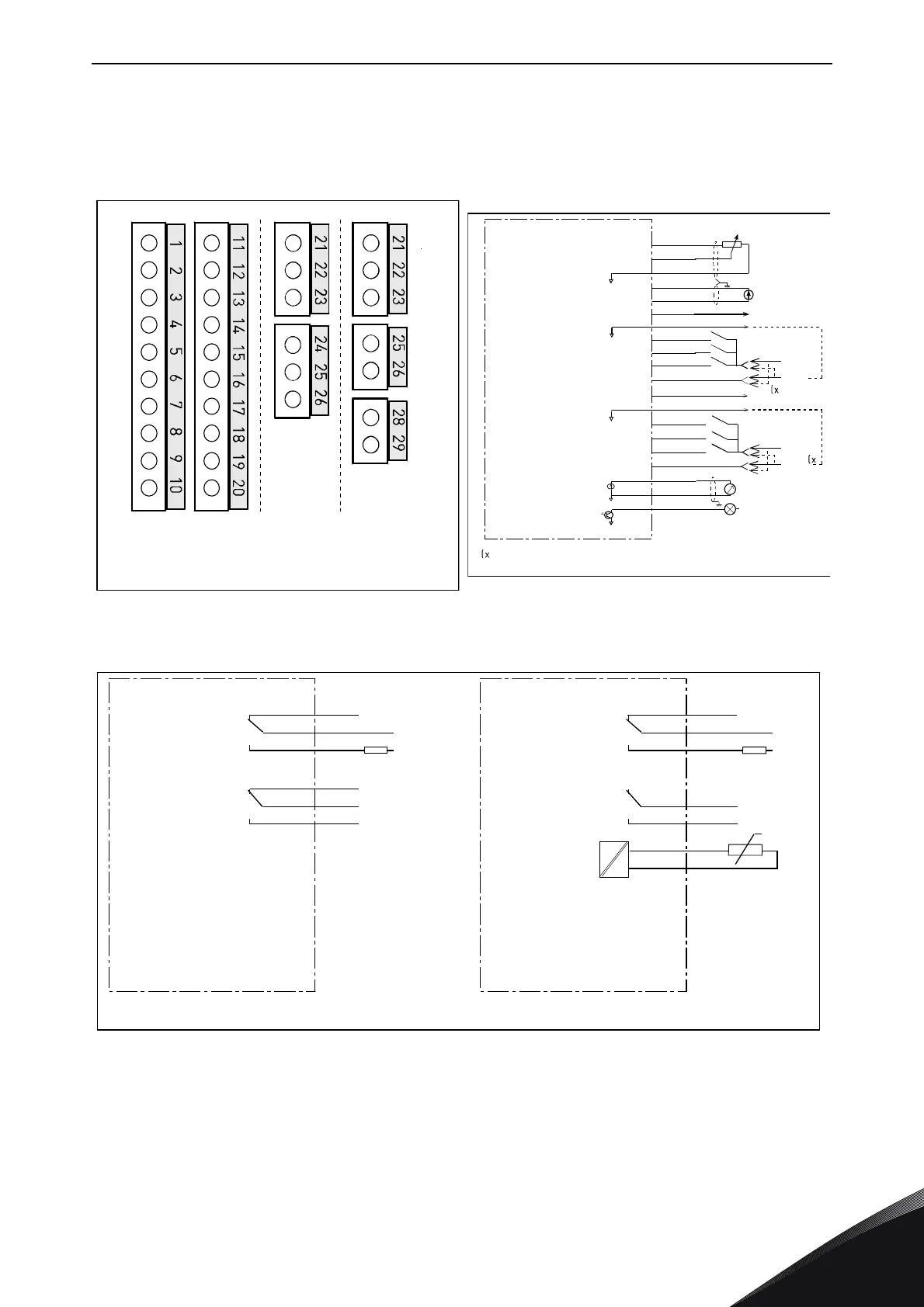
8.2.1 Control connections
The basic control connections for boards A1 and A2/A3 are shown in Chapter 8.2.2.
The signal descriptions are presented in the All in One Application Manual.
Figure 35. General wiring diagram of the basic relay boards (OPT-A2/OPT-A3)
Figure 33. The I/O terminals of the basic
boards
Figure 34. General wiring diagram of the basic
I/O board (OPT-A1)
OPT-A2 OPT-A3
Board OPT-A1
in slot A
Boards OPT-A2 and
OPT-A3 in slot B
11515_uk
+10Vref
AI1+
GND
AI2+
AI2-
24Vout
GND
DIN1
DIN2
DIN3
CMA
24Vout
GND
DIN4
DIN5
DIN6
CMB
AO1+
AO1-
DO1
1
2
3
4
5
6
7
8
9
10
11
12
13
14
15
16
17
18
19
20
24 V
GND
24 V
GND
U<+48V
I<50mA
+
0(4)/20mA
R
C
<500
Basic I/O board
OPT-A1
Reference
(voltage)
Reference
(current)
Dotted line indicates the connection with inverted signals
11516_uk
RO1/1
1/2
RO1/3
RO2/1
2/2
RO2/3
ac/dc
21
22
23
24
25
26
21
22
23
25
26
RO1/1
1/2
RO1/3
2/1
RO2/2
ac/dc
28
29
TI1+
TI1-
+t
Switching:
<8A/24Vdc,
<0.4A/125Vdc,
<2kVA/250Vac
Continuously:
<2Arms
Basic relay board
OPT-A2
Switching:
<8A/24Vdc,
<0.4A/125Vdc,
<2kVA/250Vac
Continuously:
<2Arms
Basic relay board
OPT-A3
11517_uk