6
vacon • 34 CABLING AND CONNECTIONS
Tel. +358 (0) 201 2121 • Fax +358 (0)201 212 205
6.2 Power connections
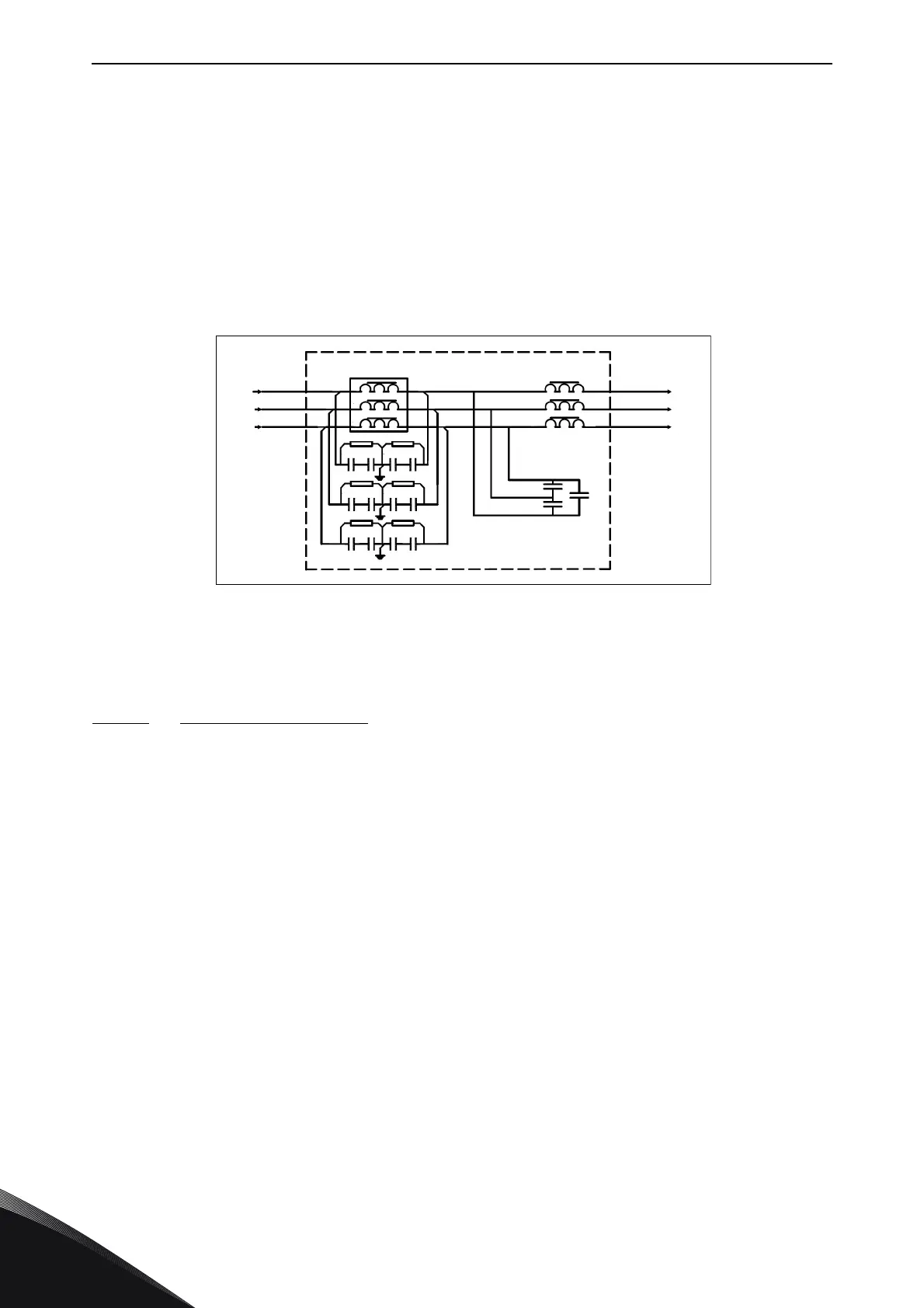
6.2.1 LCL filter wiring diagram of NXC low-harmonic drive
The LCL filter in the NXC low-harmonic drive contains a choke on the mains side, capacitors and a
choke on the AFE side. The LCL filter also includes capacitors connected against ground potential.
There are resistors connected across the capacitors for discharging these when the LCL filter is
disconnected from the input power.
Figure 11. Vacon LCL filter wiring diagram
6.2.1.1
Removing HF capacitors
If a PWM modulated rectifier of another manufacturer is connected to the same input transformer,
the capacitors must be removed. Otherwise the capacitors must not be removed.
Figure 12 ( AF9, AF10 and AF12) and Figure 13 (AF13 and AF14) have a red marking on the lead that
has to be removed from each capacitor if the interference suppression capacitors are not to be
used. Removing the lead disconnects the capacitors from ground potential.
LCL FILTER
L1
L2
L3
U
V
W
U1
U2
V1
V2
W1
W2
-L2.1
-L2.2
-L2.3
-C1
-C2
-C3
-R1
-R4
-R2
-R3 -R6
-R5
-C2.1 -C2.2
-C5.2
-C1.1 -C1.2
-C5.1
-C4.1 -C4.2
-C3.1 -C3.2 -C6.1 -C6.2
-L1
11181_emf